A hydraulic schematic of principle reads in three layers: the generator, the decoupling device, the secondary circuits. What changes from one configuration to the next is the middle layer, and it is the one that decides everything else: a heat pump buffer tank piped in series on the return adds water volume, while the same tank with four connections decouples the heat pump from the emitters. The flow of each branch then follows from output and the chosen ΔT, with Q (m³/h) = P (kW) / (1.163 × ΔT), so 1.72 m³/h for a 10 kW heat pump at ΔT 5 K. On the hot water side, article 36 of the French arrêté of 23 June 1978, as amended in 2005, requires at least 50°C at every point of a distribution network holding more than 3 litres, and at least 55°C at the outlet of storage of 400 litres or more: those figures set where the cylinder, the recirculation loop and the blending valve sit on the schematic.
Reading a hydraulic schematic of principle
The symbols and connections to identify first
On a hydraulic schematic, start by identifying the flow and the return, with the arrows giving the direction of circulation. A tapping marks a branch to an emitter or a loop. A bypass is an alternative path, used to guarantee a minimum flow rate or to isolate a device without shutting the system down.
The components that structure the reading
The circulator carries the flow: its position relative to the generator and the decoupling device conditions everything else. Valves isolate, adjust or balance. The check valve prevents backflow when a circuit stops. The air vent releases air, the relief valve protects against overpressure. Identify these components and their direction before touching any setting.
What a schematic of principle does not tell you
A schematic of principle gives the topology, not the diameters or the pressure losses. On site, confirm the diameters actually installed, recalculate the pressure loss of the least favoured circuit and compare it with the available head. A check valve fitted backwards is enough to produce noise, a flow fault and a heat pump in safety mode.
The 10 standard configurations and their key device
The selection table
Each configuration comes down to one central device. These are the ten arrangements that cover most domestic retrofit work.
| Configuration | Key device on the schematic | When to use it |
|---|---|---|
| 1. Heat pump direct to radiators | No decoupling | Oversized emitters, sufficient water volume |
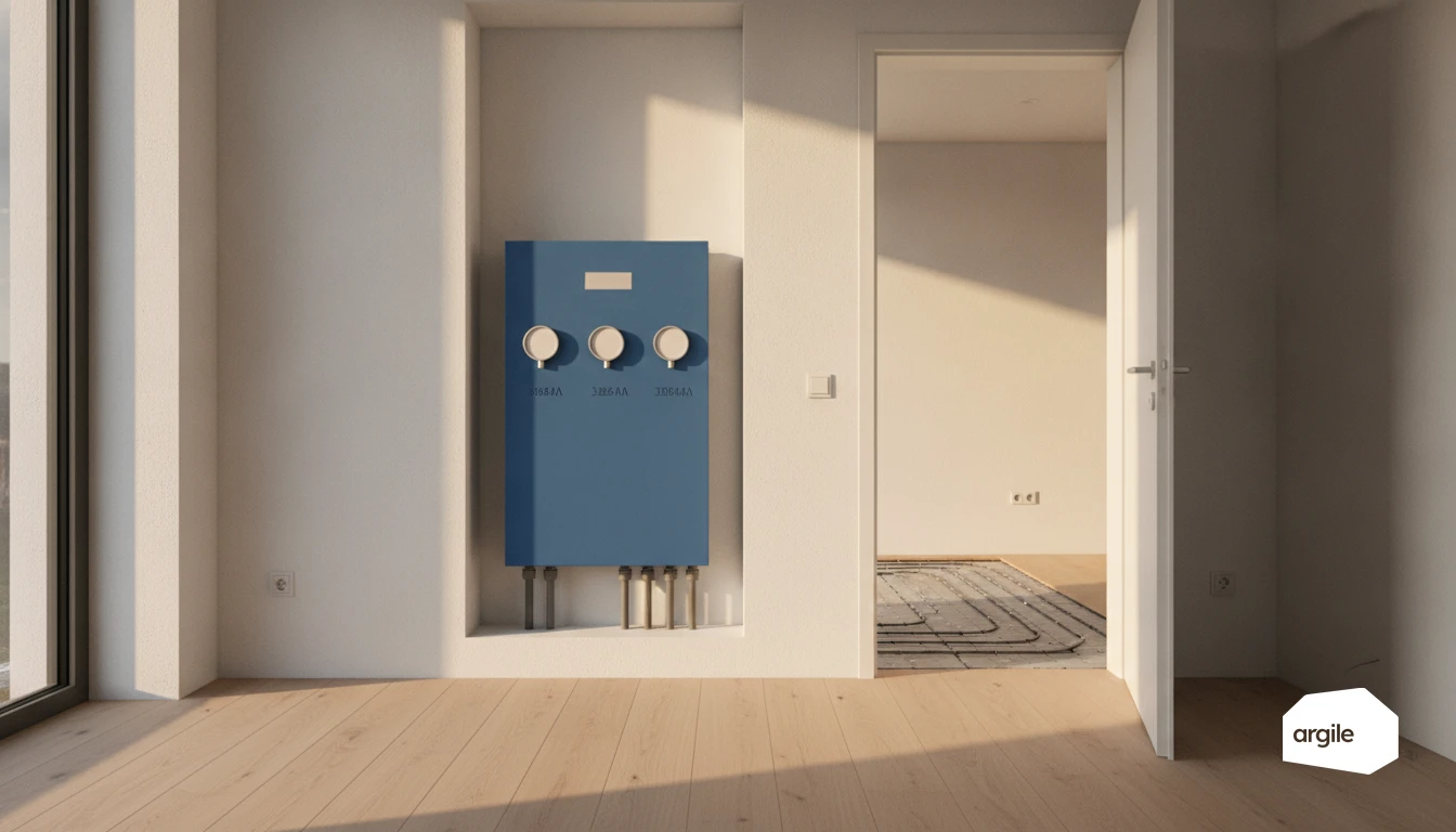
| 2. Heat pump direct to underfloor heating | Manifold with flow meters | Loops of similar length, weather compensation |
| 3. Two circuits at different temperatures | Mixing 3-way valve | Radiators and underfloor on one generator |
| 4. Heat pump + buffer tank in series | Buffer tank | Short cycling, insufficient water volume |
| 5. Heat pump + low-loss header | Low-loss header | Several circulators, mismatched flow rates |
| 6. Heat pump + coil DHW cylinder | 3-way DHW priority valve | Combined heating and hot water production |
| 7. Condensing boiler direct | Unmixed low return | Existing two-pipe network with a wide ΔT |
| 8. Heat pump + boiler in backup | Generator interlock | Bivalent point, existing boiler retained |
| 9. Heat pump + wood boiler stove | Multi-source buffer tank | Wood source with non-modulating output |
| 10. Balanced DHW recirculation loop | Loop balancing valve | Long distribution runs, wait at the tap |
DHW priority and the temperatures to hold
DHW priority through a 3-way valve diverts the whole flow to the cylinder during a charge, which assumes the heating can wait. The schematic has to show the blending valve at the outlet and, on a recirculated network, the loop balancing valve. The anti-legionella cycle is driven from the controls, not from a permanently high setpoint.
Buffer tank wiring diagram for a heat pump: in series or with 4 connections
A buffer tank can be connected in two ways that do not do the same job. In series on the return, with two connections, it adds water volume without separating anything. In parallel with four connections, it becomes a low-loss header with volume. The question to ask on the survey: is volume missing, or can the two sides not run at the same flow rate?
Buffer tank in series on the return (2 connections)
- The heat pump feeds the emitter flow directly, radiators or underfloor manifold.
- The emitter return enters the tank through one connection and leaves through the other, at the opposite end.
- The water goes back to the heat pump inlet, with the filter and isolation valves upstream.
- A single circulator, the heat pump's: the flow rate is the same everywhere.
On the return, the tank stays at the lowest temperature in the circuit: it loses less and does not delay the emitters. Its volume adds to the network's. Its limit: when thermostatic heads close, the heat pump's flow drops with the network's, hence a bypass or a differential pressure regulator.
Buffer tank in parallel with 4 connections (decoupling)
- Primary loop: heat pump flow at the top, return to the heat pump at the bottom, on the same side.
- Secondary loop: emitter flow drawn at the top on the opposite side, return at the bottom.
- One circulator per loop, and a check valve on each secondary circuit.
- The two flow rates can differ: the difference passes through the volume.
The setting that decides everything: a primary flow slightly higher than the secondary. If the network draws more than the heat pump supplies, the tank recirculates return water into the flow and the emitters get water that is too cold. If the primary is far higher, hot water goes back down to the heat pump, its COP drops and it stops too early.
| Criterion | Buffer in series on the return | 4-connection buffer | Low-loss header |
|---|---|---|---|
| Circulators | A single one, the heat pump's | One per loop | One per loop |
| Adds usable volume | Yes, to the network | Yes, for the heat pump alone | No |
| Separates flow rates | No | Yes | Yes |
| Typical case | A single low-volume circuit | Several circuits, zoned network | Mismatched flows, enough volume |
When a buffer tank is really useful
| Situation | Without a buffer | What the buffer brings |
|---|---|---|
| Water volume below the heat pump manual's minimum | Constant restarts | Longer cycles |
| Defrosting an air-to-water heat pump | The heat pump draws its heat from the circuit, the flow temperature drops | A reserve that absorbs the cycle reversal |
| Zoned emitters | Active volume and flow shrink when zones close | A volume independent of the zones |
| DHW in priority on the same heat pump | Heating stopped during the charge | Emitters still supplied |
It is unnecessary on a large unzoned underfloor system, already rich in water, and often on an inverter heat pump that modulates low. For defrosting, note that with four connections the heat pump only sees its primary loop: the tank alone has to cover the manufacturer's minimum volume, so it is often larger than in series.
Heat pump and underfloor heating hydraulic diagram
A mixing valve is only needed if water hotter than the floor accepts can reach it. NF DTU 65.14 limits the flow temperature of underfloor heating to 50°C; a low-temperature heat pump controlled by a heating curve stays below it and feeds the floor directly.
Floor alone on a low-temperature heat pump: direct connection
- Heat pump flow to the manifold, through an isolation valve.
- Manifold with flow meters, one loop per room, balanced at commissioning.
- Return to the heat pump through a magnetic filter and a dirt separator.
- Safety thermostat on the flow, cutting the circulator in case of overheating.
If the loops are controlled by motorised heads, check the remaining volume when most of them are closed: that is where a buffer in series or a bypass becomes necessary.
When the mixing valve becomes necessary
| Situation | Mixing valve | Associated device |
|---|---|---|
| Floor alone, low-temperature heat pump | No | Safety thermostat |
| Floor and radiators on the same heat pump | Yes, on the floor | 4-connection buffer or header |
| High-temperature heat pump or backup boiler | Yes | Flow sensor downstream of the circulator |
| Wood boiler stove or multi-energy tank | Yes | Buffer tank and wood safeties |
The valve installation is described step by step in our article on 3-way valves, and the choice of machine in air-to-water heat pump and underfloor heating.
The hot water temperatures that constrain the schematic
What the amended arrêté of 23 June 1978 sets
Article 36 sets thresholds that directly determine where components sit on the schematic. They apply to dwellings, workplaces and buildings open to the public.
| Point of the network | Requirement |
|---|---|
| Distribution network holding more than 3 litres | At least 50°C at every point, excluding final draw-off pipes |
| Outlet of storage of 400 litres or more | At least 55°C permanently, or a daily rise as set out in annexe 1 |
| Draw-off points in rooms used for washing | 50°C maximum |
| Draw-off points in other rooms | 60°C maximum |
Annexe 1 of the arrêté of 30 November 2005 gives the accepted temperature and duration pairs for the daily rise: it has to be read in the text itself, since the duration varies with the temperature reached.
What those thresholds impose on the schematic
Two opposing requirements coexist: produce and store hot for the sanitary risk, distribute tempered for the scalding risk. The schematic reconciles them with a thermostatic blending valve at the outlet of production, not by lowering the storage setpoint. On a cylinder fed by a heat pump, that constraint also weighs on the choice of electric backup.
DHW recirculation: length, balancing and control
A recirculation loop cuts the wait at the tap but requires the temperature to hold at every point of the loop. Insulate, limit the loop to the sections that need it, fit balancing devices on each riser and interlock the pump. An unbalanced loop creates cold branches that become the sanitary weak point of the network.
Configurations with a heat pump and mixed generators
Heat pump direct: feasibility conditions
Connected directly to radiators or underfloor heating, feasibility rests on the flow temperature the emitters accept and on the available water volume. Check the manufacturer's minimum flow, the balancing of the network and the consistency of the ΔT. Key settings: weather compensation curve, an appropriate circulator speed, a magnetic filter protecting the heat exchanger.
Heat pump and boiler in backup: control logic
The heat pump covers the base load, the boiler takes over at the bivalent point defined at the sizing stage. On the hydraulic side, plan for check valves, a 3-way valve or decoupling through a tank depending on the flow rates involved. The control logic must interlock both generators to rule out double heating, and keep priority on the heat pump for as long as the outdoor temperature allows.
Heat pump and wood boiler stove: decoupling and wood safeties
With a non-modulating wood source, the circuits are separated by a buffer tank that absorbs the output peaks. The schematic has to show the thermal relief valve, the cooling loop and the overheat safety, all non-negotiable on a solid fuel appliance. Add a dirt separator and an air vent at the high point of the primary.
Common mistakes on a schematic with a buffer tank
| Mistake | Symptom | Fix |
|---|---|---|
| 2-connection buffer fitted to decouple two circuits | Circulators fighting each other | Switch to 4 connections or add a header |
| Secondary flow higher than primary | Emitter flow too cold | Turn down the distribution circulator |
| Primary flow far higher than secondary | Hot return, short cycles | Bring the primary back within the manufacturer's range |
| Top and bottom connections swapped | Stratification destroyed | Flows at the top, returns at the bottom |
| Heat pump sensor badly placed | Stops on a temperature that is not the emitters' | Immersion pocket or flow, as per the manual |
| Uninsulated tank outside the heated space | Permanent losses | Insulated tank, in the heated space |
Commissioning and handover of the schematic
Labelling and refilling
Before restarting, label the flows, returns and adjustment devices, then vent methodically from the high point down to the generator. Check cold pressure and tightness before any rise in temperature. An air pocket at the high point skews the balance and makes the circulator work in cavitation.
Commissioning checks
Measure flow, return and ΔT on each circuit, compare with the design ΔT, then record the flow rates at the manifold and log them in your plumber software with the chosen diagram. Set the circulators to a fixed speed or constant pressure depending on the network type. A correctly set schematic shows quickly: less noise, even temperatures, longer generator cycles.
The as-built schematic as a file document
The schematic of principle used at the design stage is not the deliverable. What you hand over is the as-built schematic, labelled, dated and signed, together with the sizing note, which Argile produces to EN 12831-1 from the survey readings, and the commissioning readings. It is the document that lets another installer take over the system without rediscovering it, and the one that protects you if the configuration is ever challenged.