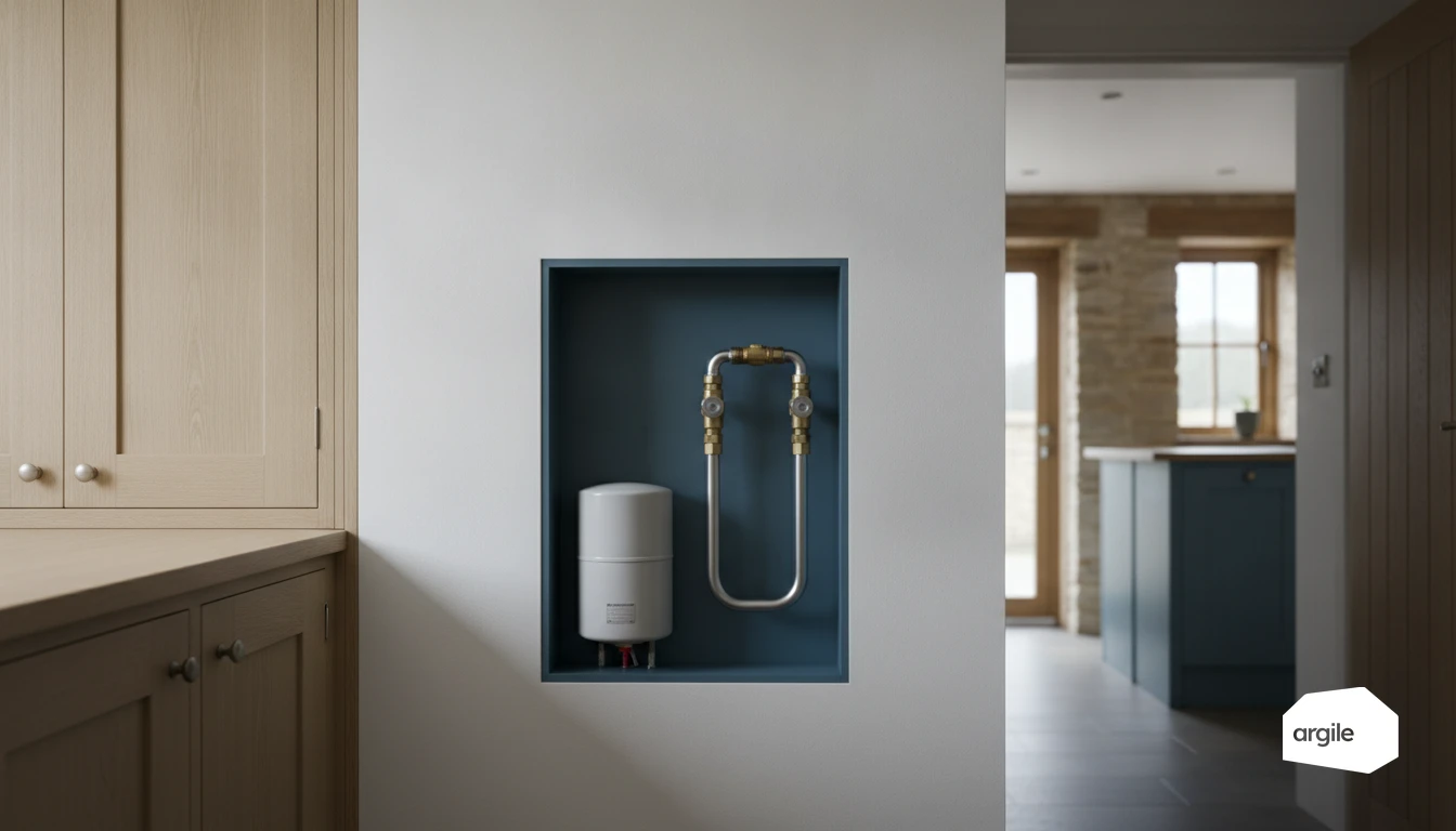
Sizing a hydraulic separator starts from the total flow rate of the circuit, in m³/h: the internal diameter is chosen so the water velocity stays low inside the separator, and the height is taken at 3 to 5 times that diameter so flow and return do not mix. Common volumes in a house run from 5 to 30 litres. An undersized separator shows up as unstable temperatures, noise and short cycling on the heat pump, an oversized one as a slow temperature rise and settings that will not hold. The pressure drop quoted at the design flow rate and the centres of the tappings are checked before ordering, because they are what decides whether the two circulators work together or against each other.
Understanding what a hydraulic separator does in a heating system
The role of primary/secondary decoupling: stable flow rates and temperatures
A hydraulic separator hydraulically splits the generator circuit (primary) from the emitter circuit (secondary). The result: each keeps its own flow rates without disturbing the other. When flow rates differ, the separator lets part of the water return to the return line or mix. You gain a more stable flow temperature and fewer risks of noise, pumps "fighting" each other, or short cycling.
When the separator becomes essential on site: heat pump, boiler, multi-zone networks
It quickly becomes useful with a heat pump that needs a stable minimum flow rate, a boiler protected by a dedicated circulator, or a network with several zones and circulators. As soon as there are closing valves, an underfloor circuit plus radiators, or variable flow rates, the separator acts as a hydraulic buffer. For similar cases, the hydraulic by-pass to protect the heat pump from low flow rates addresses the same need to maintain a minimum flow rate.
Difference from a simple manifold: what the separator really brings
A manifold just distributes water, full stop. The separator, on the other hand, creates a very low pressure-drop zone that enables decoupling and mixing. In its equipped version, it also helps vent air and trap sludge, for a more stable circuit. It does, however, let the two waters mix: when the circuits must stay separate (pressure, glycol, dirty water from an old system), what you need is a plate heat exchanger, with the temperature approach it imposes.
Sizing your separator correctly: simple rules and common mistakes
Choosing the diameter and height: practical benchmarks based on total flow rate
Start from the total flow rate of the circuit (m³/h). The goal is simple. Inside the separator, keep the water velocity low so hydraulic decoupling can do its job. In practice, the target is 0.1 m/s, which an internal diameter of at least three times the main pipe delivers on its own. Choose the internal diameter accordingly. On the height side, a separator that's too short mixes flow and return. A common benchmark is a height of about 3 to 5 times the diameter, with well-aligned connections.
Pressure drop, water velocity, noise: points to check before ordering
Before ordering, check the pressure drop stated at the design flow rate. It must stay low to avoid circulators "fighting" each other. Also check the connection spacing and the fitting diameter. If velocity is too high, noise increases and air gets re-entrained.
- Flow rate and ΔT consistent with the power output (heat pump, boiler, network).
- Provision for air venting and sludge settling where needed.
Oversizing or undersizing: symptoms and fixes
An undersized separator shows up as unstable temperatures, noise, or short cycling on the heat pump. Conversely, an oversized separator can slow the temperature rise and complicate settings. Fix it by adjusting circulator speeds, balancing flow rates, or changing diameter if the problem is structural.
Primary/secondary connection diagrams: a clean, readable layout
Connection positions, flow direction and circulator balance
On a separator, keep the primary connections facing the secondary connections. Flow at the top, return at the bottom, with a consistent flow direction on each loop. The goal is to decouple the flow rates. The primary circulator secures the generator's flow rate. The secondary circulators drive the emitters without overpowering the primary pump. If a secondary circuit draws more, the separator mixes, that's normal.
Air vent, drain, dirt separator: where to place them around the separator
Plan an automatic air vent at the top of the separator. Place a drain at the bottom, with isolation valves so you can intervene without draining the whole network. The dirt separator generally goes on the return towards the generator, where the temperature is lower and particles settle out more easily.
Common cases: underfloor heating + radiators, buffer tanks, hydraulic modules
For underfloor heating plus radiators, take two secondary flows off the separator. One direct radiator circuit. One underfloor circuit with a mixing valve and dedicated circulator. With a buffer tank, keep the logic simple. Generator → separator → network, or tank on the primary side if the manufacturer requires it. For a heat pump hydraulic module, keep the separator as your reference point. Stable primary, well-matched secondaries.
Settings and commissioning: achieving effective decoupling from day one
Setting the circulators: how to avoid primary/secondary conflicts
On an installation with a separator, first set the primary circulator to the primary flow rate required by the boiler or heat pump, then stabilise that point. On the secondary side, start from a lower speed and increase it gradually until the manifolds are correctly fed, without "starving" the primary. With variable-speed circulators, avoid overly aggressive curves and check the rotation direction.
Checking proper operation: ΔT, top/bottom temperatures, no short-circuiting
At commissioning, measure the ΔT at the generator and on the secondary flow/return lines. Check the temperatures at the top and bottom of the separator. The top should stay close to the primary flow temperature, the bottom close to the return. A rapid drop in secondary flow temperature, or top and bottom temperatures that are too close, often points to a short-circuit or poor flow-rate balancing.
Troubleshooting: sludge build-up, flow-rate faults, secondary temperature swings
If the secondary temperature oscillates, start with the simple causes. Air venting, clogged filters, stuck check valves, partially closed valves. Sludge build-up shows up as a ΔT that climbs and a flow rate that collapses. Clean the strainers, check the dirt separator, flush if needed, then redo the settings. For a flow-rate fault, also check the available pressure and the network's pressure drops. To go further, see poor flow-rate balancing.
In 2026: securing your subsidy files with consistent hydraulics
Heat pump and compliance: why a well-designed separator avoids underperformance
On a heat pump, a consistent separator stabilises flow rates and limits short cycling. The result: a COP closer to the promised value, less noise and less wear. Above all, you stay aligned with the manufacturer's hydraulic diagram. This detail is often what makes the difference between an installation that's "compliant on paper" but disappointing in the field.
Funded work: evidence on the installation side (diagram, photos, manuals)
In 2026, a solid file rests on clear evidence. Keep a dated hydraulic diagram, the manufacturer's manuals and a photo record before the networks are closed up. That record belongs in the site follow-up, alongside progress and the clearing of snags.
- Clear photos of the unit, the separator, the circulators, the safety devices and the controls.
- A photo of the nameplate and the exact reference of the equipment installed.
- Commissioning report and initial settings.
Good practice: traceability of settings and explaining them to the client
What makes the difference is traceability. Note the heating curve, the setpoints, the target ΔT, the balancing, and the valve positions. Then explain to the client, in 5 minutes, what to monitor and when to schedule maintenance. A well-set-up home means a smoother funding process and fewer callbacks.