A hydraulic bypass links the flow and return of a heat pump circuit to guarantee the minimum flow rate the manufacturer requires, of the order of 30 to 60% of nominal flow. The AQC E10 pathology sheet recalls the EN 14511-2 test point for air-to-water heat pumps: water at 30 °C entering the condenser and 35 °C leaving it, a 30/35 °C regime and a 5 K difference, for a COP of 3.2 with air at 7 °C at the evaporator. At that regime, an 8 kW heat pump draws 1.38 m³/h, and the low threshold at 30% falls to 0.41 m³/h. The bypass is fitted after the generator, at a diameter at least equal to that of the network, most often as a differential pressure valve set to just the pressure needed to hold that flow. Without a bypass, thermostatic heads closing leave the circulator with no hydraulic path: the unit trips on a flow fault and strings together short cycles that wear the compressor. The setting is checked on site with the zones closed, on a flow meter or on the flow-return temperature difference, then revalidated under normal operation so the bypass does not short-circuit the network permanently. Slowing the circulator does not replace the bypass: since 1 August 2015, Regulation (EC) No 641/2009 has required an energy efficiency index of EEI ≤ 0.23 for glandless circulators from 1 to 2,500 W, and the head reserve that once masked a closed network is gone.
Understanding the hydraulic bypass and its value on a heat pump
What a bypass is for when flow drops in the circuit
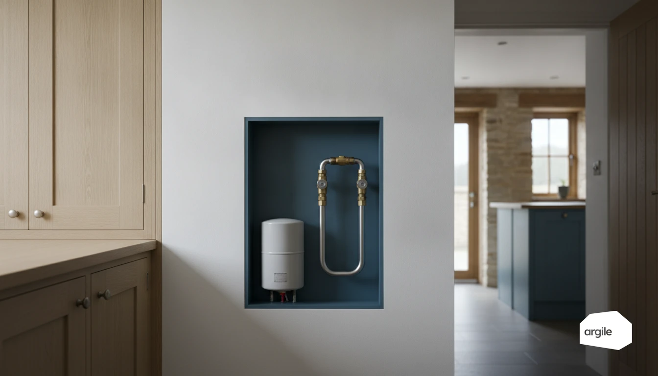
On a heat pump, the bypass is a "bridge" between flow and return. When thermostatic valves close or a zone shuts off, flow can drop. The bypass then opens to guarantee a minimum flow through the heat exchanger and stabilise the control system.
The risks without a bypass: safety, noise, wear and breakdowns
Without a bypass, the circulator has to work harder and noise increases in the pipes. The heat pump can trigger a safety cutout (flow fault, overheating or pressure) and shut down repeatedly, which wears out the compressor and components. Defrost cycles also become less effective if circulation is too weak.
The difference between a hydraulic bypass, a low-loss header and a buffer tank
The bypass maintains a water path when the network closes. The low-loss header provides hydraulic decoupling between the heat pump circuit and the heating circuits, useful with multiple circulators. The buffer tank adds volume to limit short-cycling and smooth out demand.
NF DTU 65.16 draws the boundary: it covers electrically driven compression heat pumps with a maximum nominal thermal output of 70 kW or less, and its scope stops at the start of the hydraulic network, up to the buffer tank or low-loss header if there is one. For the latter it recalls the "3d" rule, a diameter at least three times that of the main pipework. The bypass replaces neither: it guarantees a water path, not a water volume.
Spotting the situations where a bypass becomes essential
Radiators with thermostatic heads: closures and unguaranteed minimum flow
In a radiator network, thermostatic heads can close almost all the paths. The circulator ends up with no hydraulic route, minimum flow is no longer guaranteed and the heat pump or boiler can trigger a safety cutout. A bypass, often a differential type, maintains circulation when valves close and limits whistling noises.
Underfloor heating with short loops: pressure losses and unstable flow
With underfloor heating, very short or poorly balanced loops create low resistance. Flow takes the path of least resistance, the control system becomes jumpy and pressure losses vary from one loop to another. A bypass helps stabilise flow rates and protect the circulator when manifold zones close. To better understand this phenomenon, see pressure losses in hydraulic heating networks.
Renovation and extensions: mixing old and new, sludge, clogged filters
In renovations or extensions, old radiators, new emitters and accessories like the dirt separator or filter are often mixed. If the water is dirty, a clogged filter or sludge can sharply increase resistance. The bypass offers a fallback path while you purge, clean and restore more regular circulation.
Sizing and positioning a bypass to secure the minimum flow
Choosing the type: automatic (differential) bypass or manual valve
The automatic bypass (differential valve) opens when pressure rises, for example when thermostatic valves close. It maintains a minimum flow with no supervision and limits noise. The manual valve remains a simple option on small installations, but it continuously short-circuits part of the flow and can degrade efficiency if left too open.
Where to place it: flow/return, before or after circulators and control devices
Place the bypass between the hydraulic flow and return, in a zone where the pressure difference accurately reflects emitter closure. In practice, it's often placed downstream of the circulator and upstream of the devices that can close (zone valves, thermostatic heads), or on the most unfavourable loop to capture the real ΔP. On diameter, stay at least at the network calibre and keep the water velocity within the usual distribution range, 0.5 to 1.0 m/s: a bypass narrower than the network whistles and will not pass the minimum flow.
Field settings: setpoints, ΔP, and checking the manufacturer's minimum flow
Set the ΔP setpoint so it stays just enough to maintain the minimum flow required by the manufacturer (heat pump, boiler). Check on site at reduced flow (zones closed) using a flow meter, pump readout, or flow/return temperature measurement. Adjust progressively, then revalidate under normal operating conditions to avoid an overly active bypass.
Flow is calculated before it is measured, with Q (m³/h) = P (kW) / (1.163 × ΔT). At the 30/35 °C regime, a 5 K difference, an 8 kW heat pump draws 1.38 m³/h; at ΔT 10 K it draws only 0.69. The minimum flow threshold therefore moves with the heating curve, and it is that threshold which sets the target to hold when zones close.
| Flow/return difference | Flow of an 8 kW heat pump | Low threshold at 30% |
|---|---|---|
| 5 K, 30/35 °C regime | 1.38 m³/h | 0.41 m³/h |
| 7 K | 0.98 m³/h | 0.29 m³/h |
| 10 K | 0.69 m³/h | 0.21 m³/h |
Implementation and settings: a simple, effective and compliant method in 2026
Commissioning procedure: purging, balancing, temperature checks
After filling, carry out a complete purge of each loop, then stabilise the flow. On underfloor heating or radiators, adjust the balancing to prevent one circuit from starving the others. Check that the bypass is set according to the manual, to guarantee minimum flow when valves close. Finish with a check of the flow and return temperatures, and a consistent heating curve.
Tests to perform: closing emitters, ΔT measurements and anti-short-cycling checks
Progressively close the emitters, one by one, and observe the reaction. Measure the actual ΔT between flow and return under steady conditions, then compare it to the manufacturer's target. Check the anti-short-cycling protection: minimum run time, delay, and any buffer tank. If the unit starts too often, review the flow rate, setpoints and hysteresis.
2026 best practices: site traceability, manufacturer's manual, compliance file
In 2026, compliance is also about proof. Keep simple site traceability: photos, hydraulic diagram, setting records, equipment sheets, and a copy of the manual. File it all in the compliance folder, useful in the event of a scheme inspection, and for after-sales service. The simplest route is to gather photos, readings and documents as you go in the job file, rather than at inspection time.
Troubleshooting: diagnosing a poorly set or missing bypass
Typical symptoms: flow fault, high pressure, short cycles and falling COP
A missing or closed bypass is often spotted by unstable flow on the display, "flow fault" alarms and a rapid rise in high pressure. On a heat pump, this also shows up as short cycles: it starts, quickly climbs in temperature, stops, then starts again. The result is a falling COP and a client who feels the heating is "jumpy".
Common mistakes: bypass too open, wrong location, reversed check valves
Conversely, a bypass that's too open short-circuits the installation. The return becomes too hot, the heating curve loses meaning and the emitters heat poorly. Other classic mistakes: bypass fitted in the wrong location, for example too far from the heat pump or without a pressure differential. Or check valves mounted backwards, which create parasitic circulation.
Corrective actions: adjustment, balancing, chemical flushing and circulator check
Start with fine-tuning the bypass to guarantee minimum flow without short-circuiting. Check the loop balancing and that the valves are open. If temperatures "drift", plan for chemical flushing and rinsing the filter. Finish with a check of the circulator: speed, curve, mounting direction and presence of air.
Since 1 August 2015, Regulation (EC) No 641/2009, as amended by Regulation (EU) No 622/2012, has required an energy efficiency index of EEI ≤ 0.23 for glandless circulators from 1 to 2,500 W. Raising the speed to compensate for a missing bypass costs noise and short cycles, without ever restoring flow through the heat exchanger.