Balancing a heating network means sharing the flow between emitters in proportion to their output, not winding up the circulator until the last room finally warms. The only figure you can be held to comes from the French CEE sheet BAR-SE-104, annexed to the arrêté of 22 December 2014: a collective hot-water system counts as balanced when the temperature gap between the warmest and the coolest dwelling in the same building stays strictly below 2°C. The same sheet values the work at 9,800 kWh cumac per flat in climate zone H1, against three supporting documents, one of them a signed balancing grid. Balancing, in other words, is not a feeling. It is a set of readings.
Understanding balancing: the adjustment that governs network performance
What balancing actually sets on a hydraulic network
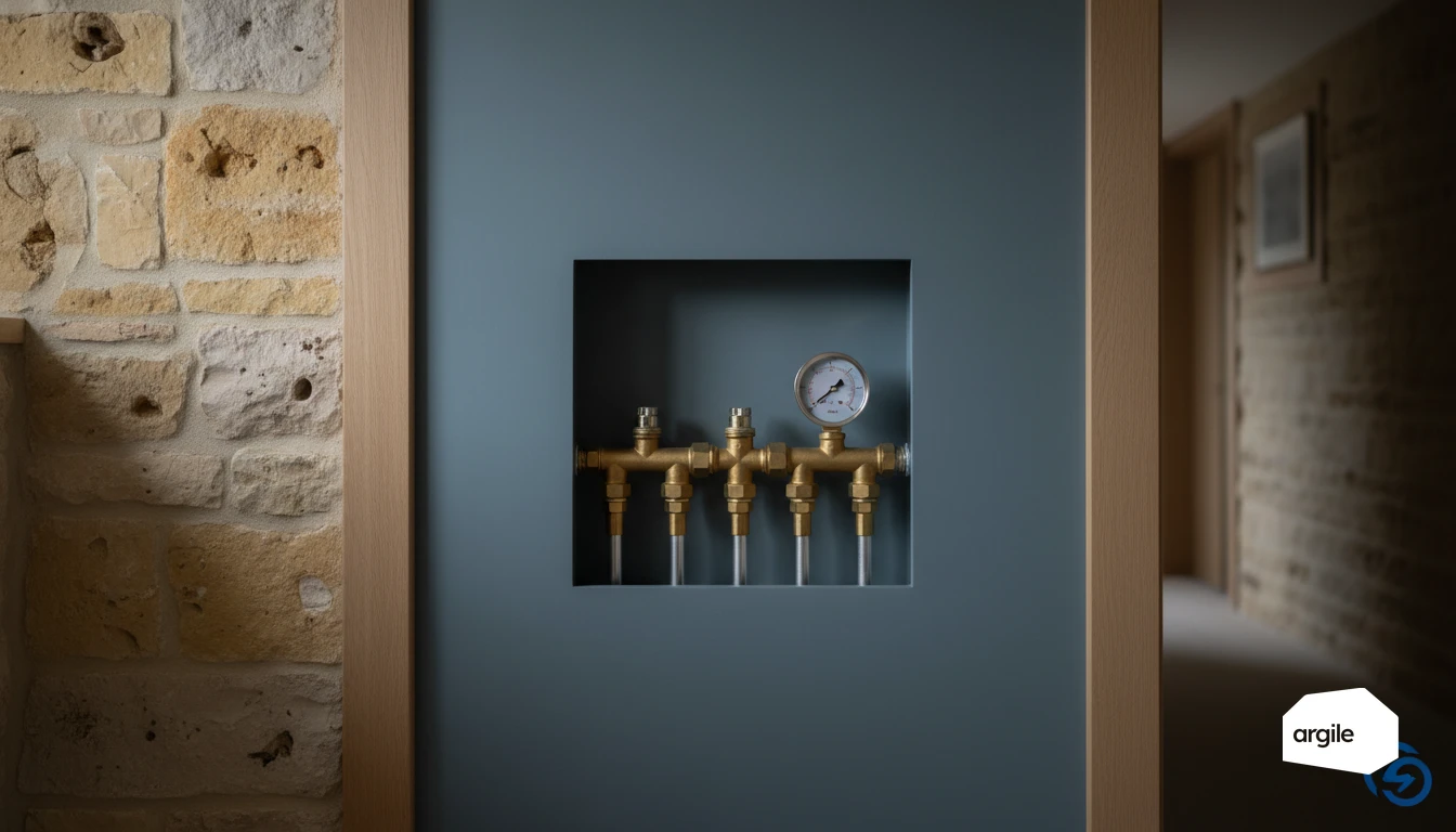
Balancing shares water flow between radiators or loops so that each emitter receives the flow matching the output it has to deliver. Without it, the emitters closest to the generator, and therefore the least resistant hydraulically, take most of the flow. The adjustment is made on the devices designed for it: valve body pre-setting, return lockshield, balancing valve, manifold flow meter.
The figure you commit to, and what it means on the quotation
The 2°C gap between dwellings set out in BAR-SE-104 is what you undertake to achieve, and what an inspection will check. It translates plainly onto the quotation: diagnosis, adjustment of the devices, before-and-after readings, handover of a signed grid. Pricing a balancing job with no line for readings means selling a service you cannot defend if it is disputed.
Balancing, bleeding and flushing: three jobs not to confuse
Bleeding clears air. Flushing removes sludge and oxides. Balancing sets the flow rates. The order is not negotiable: you balance a network that is already clean and bled, otherwise the pre-settings are made on a transient state. An automatic air vent at the high point belongs to the preparation, not to the balancing itself.
Preparing the job: network survey and baseline measurements
Surveying the network before you start: what to record and why
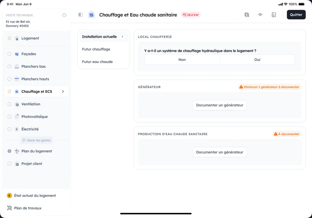
Before touching a single device, carry out the survey. Plant room, manifolds, risers, visible lengths and diameters, then every emitter with its rated output, its valve type and its reference number, recorded and photographed on site from the phone. That survey earns its keep twice: it lets you calculate the target flow of each emitter, and it becomes the simplified hydraulic diagram the funding file requires.
Measuring before adjusting: ΔT, pressure, ΔP and the flow rates you can read
Record flow and return temperatures by zone, circuit pressure, circulator speed or ΔP, and the flow rate wherever a flow meter exists. One room temperature reading per room, taken in a stable regime, gives the starting point for the 2°C test. The distribution efficiency table is a reminder of what pipe insulation changes before flow rates even enter the conversation.
Target flow per emitter: the calculation that drives the pre-setting
An emitter's flow follows from its output and the design ΔT, with Q (m³/h) = P (kW) / (1.163 × ΔT). A 1.5 kW radiator on a 45/35 regime, so at ΔT 10 K, calls for 0.13 m³/h. The same radiator at 80/60, at ΔT 20 K, calls for only 0.065 m³/h. That calculation, not the valves' original position, gives the pre-setting target.
| Emitter output | 80/60, ΔT 20 K | Intermediate regime, ΔT 15 K | 45/35, ΔT 10 K | Low-temperature heat pump, ΔT 7 K |
|---|---|---|---|---|
| 1.0 kW | 43 l/h | 57 l/h | 86 l/h | 123 l/h |
| 1.5 kW | 64 l/h | 86 l/h | 129 l/h | 184 l/h |
| 2.0 kW | 86 l/h | 115 l/h | 172 l/h | 246 l/h |
| 2.5 kW | 107 l/h | 143 l/h | 215 l/h | 307 l/h |
| 3.0 kW | 129 l/h | 172 l/h | 258 l/h | 369 l/h |
The right-hand column alone explains why a network that worked on a boiler no longer works after a heat pump swap: at the same output, the required flow is close to three times higher. Lockshields, valves and sometimes the pipe diameter were selected for the old regime, and balancing then stops being an adjustment and becomes a valve replacement that has to be priced into the quotation.
Carrying out the balancing on site: protocol and checkpoints
Balancing radiators: pre-setting, lockshields and the order of work
Secure the installation first: clean filter, isolation valves open, bleeding done. Work in a stable regime, with the generator running for at least twenty minutes and the thermostatic heads removed or fully open. Pre-set the valve bodies to the calculated target flow, starting with the least favoured emitters, then fine-tune on the return lockshield until you reach the expected ΔT without whistling.
Balancing underfloor heating: flow meters and settling the loops
Open every loop, set the circulator to constant pressure, then set each manifold flow meter to the calculated flow, higher on the long loops. Let it settle for 15 to 30 minutes before going round again. A loop closed too far does not just create a cold zone: it pushes its flow onto its neighbours and shifts the whole setting.
Circulator and heating curve: don't compensate a setting fault with head
Since 1 August 2015, Regulation (EC) No 641/2009 has required an energy efficiency index of EEI ≤ 0.23 for glandless circulators from 1 to 2,500 W. The old oversizing margin is gone: winding up the speed to hide an imbalance is paid for in noise, auxiliary consumption and short cycling. Pick the lowest speed that holds the target flow rates, and read up on the hardware in the article on variable-speed circulators. The heating curve comes next, with an outdoor sensor and the shallowest slope compatible with comfort.
Devices, hardware and the CEE allowance for balancing
Choosing the devices: balancing valve, flow limiter, ΔP regulator
A balancing valve with pressure test points lets you measure flow instead of estimating it. A flow limiter holds the setpoint despite variations in upstream pressure. A differential pressure regulator at the foot of a riser prevents whistling when the thermostatic heads close together. All three are chosen on Kv, not on pipe diameter.
The BAR-SE-104 allowance by climate zone
BAR-SE-104 applies to existing flats in a residential building served by a collective hot-water heating system. The allowance is per flat treated, and multiplies by the number of flats in the building.
| Climate zone | kWh cumac per flat | Example over 20 flats |
|---|---|---|
| H1 | 9,800 | 196,000 kWh cumac |
| H2 | 8,000 | 160,000 kWh cumac |
| H3 | 5,300 | 106,000 kWh cumac |
The acceptance test is the same in all three zones: less than 2°C between the warmest and the coolest dwelling. That gap also decides how credible the indices read by heat cost allocators are, and a block of flats disputes them fast when one dwelling ends up paying for a hydraulic imbalance.
Compatibility with modern generators: condensing, heat pumps, low temperature
A condensing boiler only condenses if the return really is cool, which assumes correct flow rates rather than a blanket overflow. A heat pump needs a guaranteed minimum flow and enough water volume, failing which it short-cycles. With low-temperature radiators the design ΔT narrows, flow rates rise and balancing becomes decisive. Control then plays out on the heating curve.
Handover, traceability and defending your price
Handover checks: what you measure and over what period
After adjusting, do the full round again in a stable regime: ΔT by zone, pressure, absence of flow noise, and above all room temperatures, room by room. The check happens at 24 or 48 hours, once the building is back up to temperature, not in the hour that follows the adjustment. It is that second visit that verifies the 2°C test.
The file to build: three documents, not one fewer
The funding file for a balancing job rests on a simplified hydraulic diagram identifying the devices adjusted, a balancing grid dated and signed by the installer, and a table of temperature readings taken after balancing and countersigned by the beneficiary. Add photographs of the labelled devices and of the instruments taking readings. That file is what stands up to an on-site inspection.
Justifying the price against a cheaper quote
A competitor quoting a balancing job with no readings is not selling the same thing. What you invoice is the measuring time, the target flow calculations, the two visits and the file. On a generator replacement, that line also underwrites the performance you have promised: an unbalanced network drags the real efficiency down and reopens the callbacks you had priced as closed.