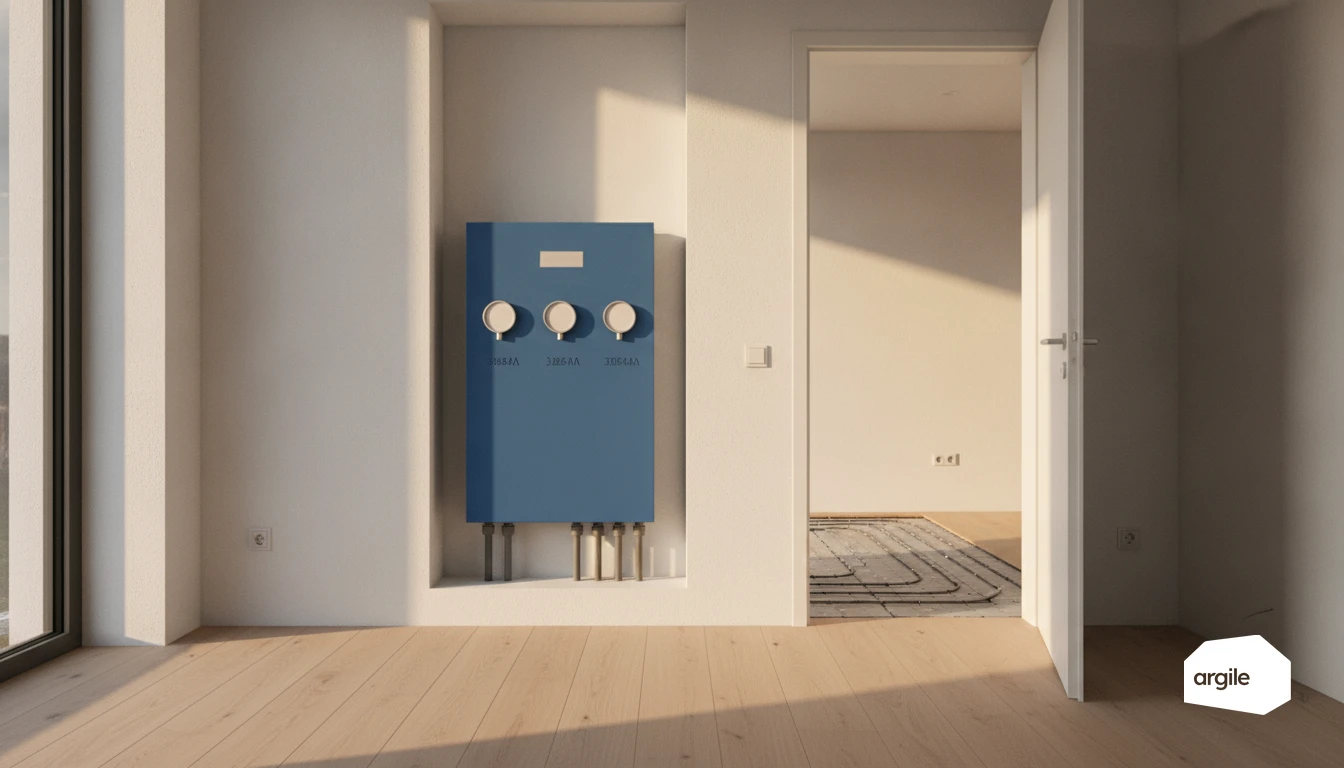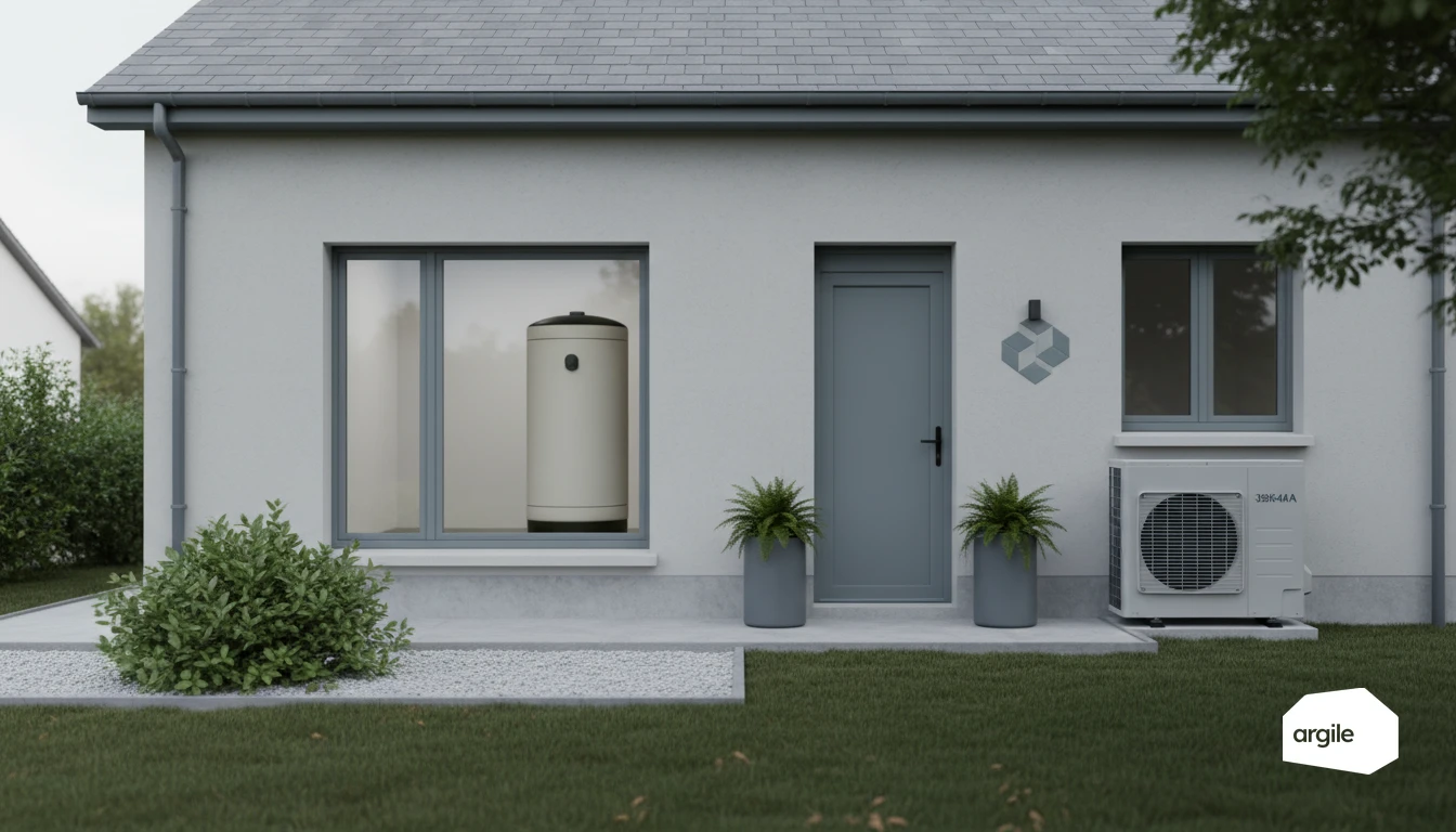
A buffer tank is not chosen by volume but by its number of ports, because that is what decides its function. France's Agence Qualité Construction is explicit: a two-port buffer tank limits the short cycling of an oversized heat pump, while a four-port mixing tank exists to reconcile two water temperatures that do not match, the heat pump's and that of older emitters. Fitting one while believing you are fitting the other is the most common mistake in the whole hydraulic package.
Buffer tank: what does it actually do on a heat pump system?
Difference between a buffer tank, a hydro-accumulation tank and a hot-water tank
A buffer tank is a volume of water placed on the heating circuit. It provides thermal mass, with no domestic hot-water purpose. The hydro-accumulation tank follows the same thermal storage logic, often on a larger scale, to smooth out heat production. The domestic hot water tank, meanwhile, only serves the tap's hot water. It's designed for hygiene and temperature retention.
Role in the heat pump's cycle: limiting short cycling and stabilizing temperature
On a heat pump, the buffer tank increases the available water volume. As a result, the unit starts less often, so fewer short cycles. You gain temperature stability, especially when thermostatic valves close or several zones shut off. It also helps absorb flow-rate variations and keep operation more consistent.
When a buffer tank is essential, and when it's optional
It becomes essential if the manufacturer requires a minimum water volume, if the system is heavily zoned, or if the network holds little water (small radiators, many thermostatic valves). It's often optional on a properly sized underfloor heating system, or on an inverter heat pump with a simple, open circuit. A poorly sized tank can add losses and slow down the heating response.
Three configurations make it necessary, and each can be spotted at survey.
- A network with little water. Short underfloor loops, small zones, radiators fitted with thermostatic heads. The heat pump reaches its setpoint quickly and restarts constantly; when the heads close, the flow collapses. The tank supplies the water volume, secures the minimum flow and protects the compressor.
- Several circuits on different controls. As soon as temperatures differ, underfloor and radiators, zones, a mixing valve, the tank provides hydraulic separation. Each pump works on its own circuit without disturbing the heat pump, and the settings become readable again.
- Heat pump in backup or hybrid mode. The tank acts as the meeting point between generators, eases changeovers, avoids control conflicts and smooths peaks. With solar or a boiler stove, it stores the gains and lets you prioritise the cheapest energy.
In renovation, existing radiators are often mixed with a new underfloor loop, or an extension is connected later. The tank then acts as a neutral zone between circuits and limits flow imbalances when the demands differ widely.
Defrost: what the inertia volume absorbs
On an air-to-water heat pump, defrost phases and some restarts cause temperature swings. An inertia volume smooths those, especially if the system holds little water or if the thermostatic valves close quickly. Short cycling and the drops felt by the occupant fall accordingly.
Heating and DHW on the same heat pump: priority, changeover and holding temperature
When the heat pump covers both heating and domestic hot water, DHW production usually takes priority and heating stops during the changeover. A correctly sized buffer holds the emitter-side temperature through that window. It is not automatic, though: too much volume increases losses, and good hydraulic settings are sometimes enough.
Two ports or four: what each one solves
The two arrangements look alike on a drawing and do not serve the same purpose. The first stores volume, the second separates two circuits.
| Buffer tank, 2 ports | Mixing tank, 4 ports | |
|---|---|---|
| Function | add water volume to the circuit | hydraulically decouple heat pump and emitters |
| Problem addressed | short cycling of an oversized heat pump | incompatible temperature regimes |
| Flow | one circuit, one flow rate | two circuits with independent flow rates |
| When it is required | insufficient water volume in the system | existing radiator network retained |
| What it does not do | it does not decouple the regimes | it does not by itself increase usable volume |
A third arrangement exists and is often missing from the comparison: the low-loss header. It is the cleanest answer when flows vary widely between generator and emitters, because it decouples without storing. It does not replace a buffer tank when the problem is a lack of water volume, it solves the other half of the problem. The common variant on mixed systems is the 3-way valve switching between heating and DHW.
The selection rule is one question asked at survey: is the problem a lack of volume, or a temperature mismatch? A new underfloor system with a correctly sized heat pump needs neither. A retained radiator network with a heat pump capped at 50 °C needs the second, and sometimes both.
Why water volume decides how long the compressor lasts
The mechanism is documented and it is expensive. An oversized heat pump runs cycles that are too short, which shortens its life. At the other end, an undersized one runs continuously, which increases the number of defrost cycles, degrades efficiency and can go as far as compressor failure, or icing up altogether.
In other words the buffer tank is not a comfort accessory, it is what catches a sizing exercise with little margin for error on either side. The AQC puts checking the minimum water volume needed to avoid short cycling among the three essentials of its sheet, alongside correct sizing and servicing.
Two consequences for your quotation. The tank is priced at heat loss calculation stage, the one Argile draws from the survey readings to BS EN 12831-1, not afterwards when the client complains about the noise at start-up. And if you retain older emitters, write into the quotation which water temperature you are guaranteeing, because it is that temperature, not the output, that decides whether the client is warm in February.
Properly sizing your heat-pump buffer tank: volume, power and needs
Sizing methods: rule of thumb (litres/kW) and the stored-energy approach
For a buffer tank, a common rule of thumb is to aim for 10 to 20 litres per kW of power, especially when you want to limit short starts. To refine it, think in terms of stored energy.
Accounting for emitter type: underfloor heating, radiators, fan coil units
Underfloor heating already has a lot of water volume and thermal mass. The buffer tank can often stay modest, or even become unnecessary depending on the hydraulics. With radiators, the volume is more variable. Fan coil units hold little water and have fast-changing needs. A buffer helps stabilize the heat pump, especially in mid-season. Typical cases to validate on site.
Avoiding oversizing: thermal mass, losses, space and cost for the customer
The goal remains a right-sized volume. Enough to protect the compressor and balance the flow rates. Not so much that you're heating a tank "for nothing." Right-sized volume, better comfort.
Heat storage and hydraulics: effective layouts with a buffer tank
In-line or parallel mounting: impact on flow rate, control and comfort
With a buffer tank, mounting it in-line favours a stable delta T and limits short starts. In exchange, the flow temperature can vary if the emitters draw heavily. Parallel mounting makes room-by-room control easier and stabilizes the flow, but requires a real priority logic to avoid unnecessary mixing.
Managing flow rates: hydraulic decoupling, circulator(s) and balancing
The right instinct is decoupling between the generator and the network. One circulator on the production side, one on the distribution side, then balancing the loops (measured flow rates, adjustment valves) to avoid overly hot returns and hydraulic noise. You gain in comfort and efficiency, especially with underfloor heating.
Insulating the tank and losses: good installation practices in 2026
In 2026, aim for continuous insulation of the tank and its connections. Reduce the length of uninsulated pipework, fit insulating sleeves, and avoid untreated cold rooms. A simple heat leak is like a small lamp left on day and night in the boiler room.
Combining heat pump and wood: the buffer tank as the central storage point
Heat pump + wood boiler or back-boiler stove: safety devices, valves and operating priority
The most robust setup makes the buffer tank a hydraulic "crossroads." The wood boiler or back-boiler stove charges the tank, and the heat pump then feeds the heating circuit. Plan for suitable check valves, a relief valve and expansion vessel, and a control system that enforces wood priority to avoid unnecessary heat-pump starts.
Storage strategies: charge the tank with wood, finish as needed with the heat pump
In practice, the tank is charged to a high temperature with wood, then the stored energy is "drawn down" to last several hours. When the top sensor drops below the setpoint, the heat pump takes over as backup, with temperature sensors at the top and bottom to control finely and limit short cycling.
Points of caution: condensation, minimum temperature, anti-overheating and local regulations
With wood, watch for too-cold return water. An anti-condensation valve helps maintain a minimum temperature and limit tar buildup and corrosion. Add anti-overheating protection (thermal relief valve, backup circulation) and check local rules on wood heating and the placement of the heat pump's outdoor unit.
Field arguments and pricing: what the buffer tank changes for your jobs
Measurable benefits: comfort, fewer starts, lifespan, consumption
On a heat pump, the buffer tank acts as a hydraulic reserve. On the ground, the result is a more stable temperature, fewer swings in the rooms, and above all fewer short cycles when thermostatic valves close or the network holds little water. You gain in reliability, with a less-stressed compressor and settings that are easier to hold over time.
Deciding on site: the signs, then the checks
Four signals justify raising the tank question before measuring anything: short cycling, meaning closely spaced starts, hydraulic banging, an unstable indoor temperature, and fault codes tied to flow. An inconsistent flow-return delta T, or radiators lukewarm then scalding, point to the same cause.
The checks, in this order
- Measure the real water volume of the network and compare it with the manufacturer's requirement.
- Check the actual flow, so the pump, the filters, the dirt separator and the air purge.
- Check that valves are open and check valves are the right way round.
- Redo the balancing and find the thermostatic heads that are throttling.
- Adjust the heating curve, the hysteresis and the pump speed.
The tank is decided after those settings, not instead of them.
Common mistakes to avoid: poorly placed sensors, flow rates too low, uncontrolled mixing
The classic trap is a poorly placed sensor that "tells" the control system the wrong temperature. Another point: a stable flow rate must be guaranteed on the generator side, otherwise the heat pump starts cycling or trips into fault. Finally, if mixing between circuits isn't controlled (valves, connection points, balance), the buffer tank can become a useless radiator.
2026 funding and requirements: consistency with a whole-house retrofit, certification, and customer expectations
In 2026, your customers compare quotes on overall consistency. A buffer tank makes its case when it secures operation and limits callbacks. On the funding side, the schemes require installation by a certified installer for the measure concerned. Clear sizing, a clean hydraulic diagram and a documented commissioning often make the difference.