A three-way valve does one of two things, never both: it mixes two flows to obtain an intermediate flow temperature, or it diverts one flow to one circuit or another. On the diagram, everything reads off the three markings on the body: AB is the common port, A and B the other two. Fitting a diverting valve where a mixing valve was needed removes all temperature control, and it shows up the day the heating curve never drops below the machine's own flow temperature.
Three-way valve: diagram and role of ports A, B and AB
The diagram of a three-way valve comes down to three connections and a direction of flow. AB is the common port, through which the whole flow passes; A and B are the branches, which both come in when mixing and one or the other goes out when diverting.
| Port | In mixing (2 inlets, 1 outlet) | In diverting (1 inlet, 2 outlets) |
|---|---|---|
| A | inlet for hot water from the generator | outlet to the first circuit (often the hot water cylinder) |
| B | inlet for recirculated return water | outlet to the second circuit (often the heating) |
| AB | outlet for blended water to the circulator and emitters | inlet for water from the generator |
Some manufacturers number the ports or assign the hot water to B: the manual prevails, and the labelling used on site goes onto the diagram handed to the client.
Schematic of a mixing three-way valve (underfloor heating circuit)
Typical arrangement of a low-temperature circuit under a hotter generator, following the water:
- The generator flow arrives at port A.
- Port AB sends the blended water to the circuit's circulator, fitted just after the valve.
- The flow sensor sits downstream of the circulator, where the mix is uniform, then the water goes to the underfloor manifold.
- The underfloor return splits in two: part goes back to port B to be recirculated, the rest returns to the generator.
- A safety thermostat on the flow stops the circulator if the temperature exceeds the floor's limit (around 50 °C flow water for a hydronic floor, to be confirmed with the manufacturer's manual).
The more the valve opens A, the closer the flow gets to the generator temperature; the more it opens B, the closer it gets to the return temperature. The flow rate in the floor, meanwhile, stays constant.
Schematic of a diverting three-way valve (hot water priority)
This is the changeover valve that gives priority to domestic hot water. The generator flow enters at AB, port A goes to the hot water cylinder's heat exchanger, port B to the heating, and the two returns join before the generator. The motor is on/off: resting on the heating side, it switches the whole flow to A when the cylinder sensor calls for heat, then goes back.
How a motorised three-way valve works: actuator, flow sensor and heating curve
A motorised mixing valve works in a closed loop, and the chain has four links:
- The outdoor sensor measures the temperature outside, and the heating curve derives the flow temperature to aim for.
- The flow sensor measures what is actually going to the emitters.
- The controller compares the two and sends an order to the actuator: open the hot port if the flow is too cold, close it if it is too hot.
- The actuator turns the spindle, in pulses (3-point: one wire opens, one wire closes) or continuously (0-10 V signal), over a full stroke of around a minute or more.
The valve can only lower the generator's temperature: if the generator does not supply hot enough water, no setting will catch up with the setpoint. A heat pump on a single circuit often does without one, since it already modulates its own water temperature; the valve serves the second, cooler circuit. The whole thing relies on a well-placed outdoor sensor, facing north or north-west, out of the sun.
Understanding the three-way valve and its uses in heating
What a three-way valve is for: mixing, diverting and protecting the heat generator
A three-way valve manages three connections to either mix two flows to get a stable flow temperature, or divert the flow to another loop. In heating, it's often used to lower the temperature for underfloor heating, to isolate a circuit when demand drops, and to limit returns that are too cold. The result is a heat generator better protected against thermal shock and certain condensing regimes.
Where to fit it: underfloor heating, radiators, buffer tank, heat pump
It's placed near the underfloor heating manifold with a circulator, or on a radiator flow to create a low-temperature zone. With a buffer tank, it helps prioritise one circuit without disturbing stratification. On a heat pump, it's used to control two emitters or to safeguard return temperatures.
Mixing or diverting: the direction of flow decides everything
The valve body is almost identical, the direction of flow is not. A mixing valve has two inlets and one outlet, a diverting valve has one inlet and two outlets. Swapping them works mechanically and controls nothing.
| Type | Direction | What it does | Where it goes |
|---|---|---|---|
| Mixing, 2 in 1 out | hot flow plus cool return into a blended flow | lowers a circuit's flow temperature | underfloor heating, low-temperature circuit under a hotter generator |
| Diverting, 1 in 2 out | one flow to two destinations | routes the flow without changing its temperature | heating / hot water changeover, diversion to a cylinder |
| Thermostatic | mixing at a fixed setpoint | caps a maximum temperature, with no external control | underfloor protection, hot water limitation |
| Motorised 3-point | mixing driven by the controller | follows the heating curve, progressive opening | weather-compensated circuit |
| Motorised 0-10 V or modulating | mixing driven continuously | follows the curve with fine resolution | installations with several circuits |
The selection rule is one question: do I want a different temperature or a different destination? The first calls for a mixing valve, the second for a diverting valve. Everything else, actuation included, follows from that decision.
Mixing valve or diverting valve: boiler, heat pump and hot water priority
On a wall-hung boiler with a cylinder, the diverting valve is usually built into the appliance; on an air-to-water heat pump, it sits in the hydraulic module or comes as an accessory depending on the model. It controls no temperature, it chooses a destination.
The mixing valve is added on the heating circuit when that circuit must run cooler than the generator. An installation can therefore carry both: a diverting valve for hot water, a mixing valve on the underfloor circuit. A mixing valve fitted in place of the diverting one never fully shuts one side: the heating keeps part of the flow during the reheat, and the cylinder takes much longer to come up to temperature.
The recurring case: heat pump plus underfloor plus radiators
This is the arrangement that generates the most callbacks, and the valve alone does not answer it. When one machine serves two circuits at different temperatures, you have to mix for the low-temperature circuit and hydraulically decouple the two, otherwise the more open circuit takes the flow from the other.
France's Agence Qualité Construction describes the answer in its sheet on air-to-water heat pumps: depending on whether operation is alternating or simultaneous, fitting a four-port mixing tank on the hydraulic circuit may be necessary to reconcile the water temperatures of the heat pump and the emitters. In other words the three-way valve handles temperature, the tank handles flow, and confusing the two leads to stacking accessories without correcting the fault.
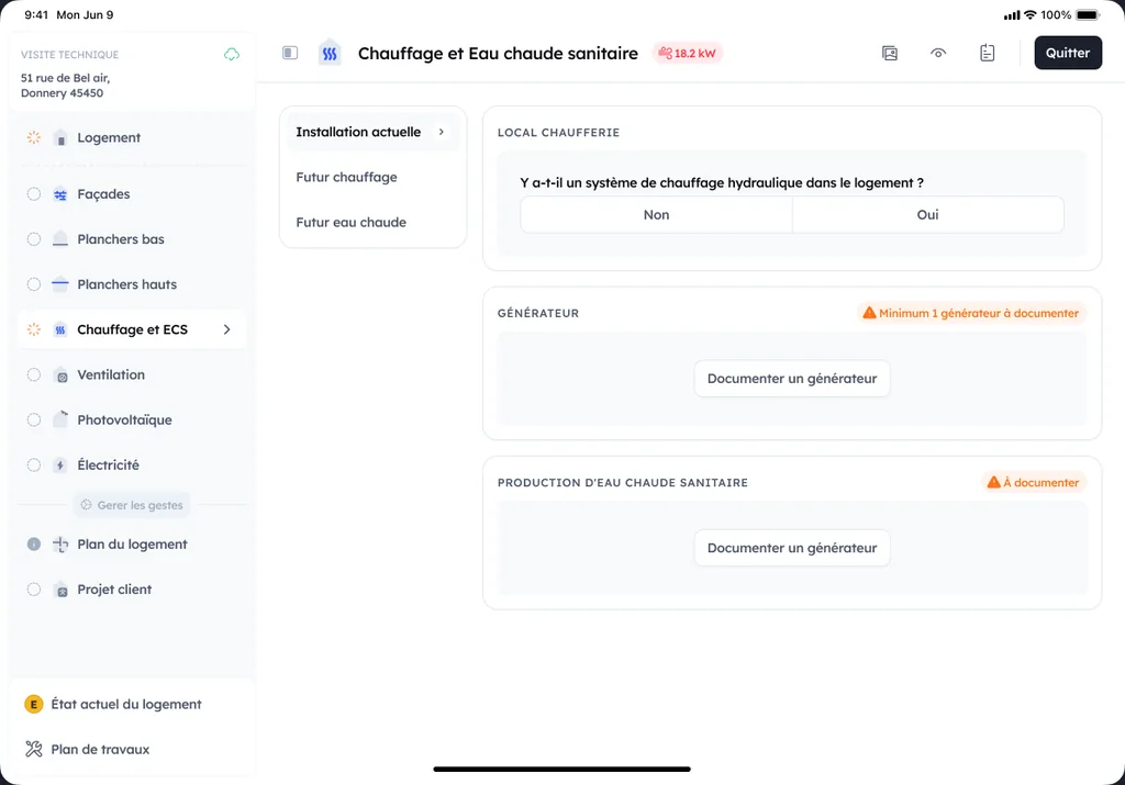
What to settle at survey, before pricing: how many circuits, at what temperatures, and do they run together or one after the other. These are three site observations, recorded during the technical visit where the engineer documents the equipment and the project step by step, not assumptions made back at the office. The answer determines the number of valves, their type, and whether a tank is needed. Settled after installation, it costs a full rework of the hydraulics.
Choosing the right valve for your installation and site constraints
Sizing and field criteria: DN, flow rate, Kv, pressure drop
On site, the valve is chosen first based on the circuit's actual flow rate and the pipe DN. Kv reflects water passage. Too low, and you choke the network. Too high, and control becomes jittery. Aim for a good Kv with a pressure drop compatible with the circulator's head, otherwise noise and imbalances show up quickly. To go further, see our article on pressure drop in hydraulic heating networks.
- Record the estimated flow rate per emitter and the flow temperature.
- Check the pressure margin available for the valve.
Compatibility and connections: threading, flanges, materials, operating temperatures
Check the connections (BSP threading, swivel nuts, flanges in the plant room) and the space needed for maintenance access. On materials, brass, bronze or stainless steel depending on water quality, glycol content, and corrosion risks. Also check the maximum temperatures and the nominal pressure (PN) stated by the manufacturer.
Control and regulation: actuator, weather compensation curve, sensor, thermostat
For a motorised valve, choose a simple control (on/off) or modulating control (0 to 10 V, 3-point) depending on the controller. In renovation, pairing a weather compensation curve, outdoor sensor and room thermostat helps maintain stable control, especially with a heat pump and underfloor heating. Plan ahead for the power supply, mounting orientation and opening time.
Fitting a three-way valve: direction, actuator position and sensor
Four points to check before refilling:
- Port direction: each connection made according to the cast markings (A, B, AB or arrows), the circulator on port AB when mixing, never on a branch.
- Actuator position: beside or above the body, never underneath, and accessible to declutch by hand.
- Direction of rotation: a rotary valve can be fitted in several orientations; set the motor so that "open" really opens the hot port.
- Surrounding hydraulics: flow sensor after the circulator, low-loss header if the generator has its own circulator, anti-thermosiphon check valve so that a circuit at rest does not heat up.
Essential settings for stable temperature control
Setting the flow temperature: setpoint, heating curve and outdoor temperatures
Start by setting the room setpoint, then adjust the heating curve to get the right flow temperature based on the weather. In mild weather, lower the slope. In very cold weather, increase it slightly. If an outdoor sensor is present, check its location (in the shade, away from an air outlet) to avoid unnecessary corrections.
Balancing the circuits: valves, flow rates, manifold and circulator settings
A well-tuned home means stable flow rates. First open the emitters, then fine-tune circuit by circuit at the manifold, with each balancing valve. The goal is to limit differences between rooms, without overworking the circulator. Too low a flow rate creates cold spots, too high can generate noise and jittery control. To go further, see the good practices for balancing a heating network.
Avoiding swings: response time, hysteresis, mounting orientation and bypass
To avoid swings, give the system time. Slightly increase the response time and hysteresis, especially with underfloor heating. Check the mounting orientation of valves and check valves. If needed, add or adjust a bypass (or a differential valve) to maintain a minimum circulation when zones close off.
Quick troubleshooting: common faults and checks to do on site
Typical symptoms: overheating, lukewarm water, noise, temperature swings
Overheating often happens when the valve stays "on the hot side" (reversed control, stuck actuator). Lukewarm water tends to point to a valve that's no longer mixing, or a parasitic flow through a check valve. A whistling or rumbling noise can come from too high a flow rate, air, or sludge choking the passage. Rapid swings indicate unstable control, or an actuator that's "hunting". First moves on site: listen, feel the upstream and downstream pipes, and note when the fault appears.
Common three-way valve faults: symptom, cause, check
| Symptom | Most frequent cause | On-site check |
|---|---|---|
| Radiators hot in summer, or lukewarm hot water cylinder | diverting valve stuck mid-stroke, motor out of order | switch over manually, measure the motor voltage during a hot water call |
| Floor too hot, flow equal to the generator's | mixing valve stuck open, direction of rotation reversed, sensor detached | read the flow sensor, operate manually, check the wiring |
| Flow never reaches the setpoint | ports A and B swapped, generator set too low, motor declutched | read the markings, compare generator flow and circuit flow |
| Temperature that hunts | stroke time wrongly set, valve too large, sensor badly placed | adjust the stroke time, move the sensor after the circulator |
Simple checks: flow direction, check valves, filter, sludge, actuator power supply
- Check the flow direction arrow and the A, B, AB markings. A reversal alone is enough to cause hunting.
- Check the check valves. A seized check valve throws off the mix.
- Clean the filter (often a Y-strainer) and bleed the air.
- Look for sludge (black water, loss of flow). A sludge trap helps.
- Measure the actuator's power supply (24 V or 230 V) and test manual mode. Flow direction.
When to replace the valve: seizing, leak, internal wear, unavailable parts
Replace the valve if it's seized despite operating it and cleaning, if it leaks (spindle, body, connection), or if internal wear produces an inconsistent mix. If the part no longer exists (obturator, seals, actuator), replacement avoids wasting hours. Also replace it when the labour cost clearly exceeds that of a new assembly.
2026 good practices: energy performance, compliance and client satisfaction
Carrying out a clean commissioning: venting, flushing, sludge removal and final settings
Before handing over to the client, secure a clean commissioning. Vent, flush the network, and run a sludge removal if the water is contaminated. Check pressure, flow rate, air vents, and the opening of each valve. Finish with balancing the emitters and the final settings of the circulator and the heating curve. To go further, rely on a checklist of essential checks to carry out.
Documenting the controls: diagram, port labelling, setpoint values and maintenance
Leave a clear client file. Hydraulic and electrical diagram, port labelling, mixing valve if present, and setpoint values. Note the heating curve, temperature limits, and the maintenance schedule. This makes RGE inspections, aid applications and repairs easier.
Optimising consumption: seasonal adjustment, night setback and temperature monitoring
Aim for simple monitoring. Adjust the heating curve each season. Use night setback with measurement, especially in a well-insulated home. Track 2 or 3 temperatures, flow, return and room, to fine-tune without overheating. Fine-tuned settings reduce kWh and callbacks.