What caps low-temperature underfloor heating is the temperature of the finished floor, not the temperature of the water. EN 1264-2 provides the limiting curves used for sizing, and some markets add a statutory cap on top: in France, article 35 of the order of 23 June 1978, still in force, forbids the finished floor from exceeding 28°C at any point. On the generator side, NF DTU 65.14 caps flow water at 50°C, a figure repeated as it stands in the AQC's E.04 pathology sheet. Sizing therefore means keeping the required output under both ceilings by working the active area, the spacing and the water regime, never by raising the temperature. In Argile's sizing note, underfloor heating is declared as a zone to heat with its area and the chosen flow temperature, and Argile derives from it the emitter coverage rate against the load calculated to NF EN 12831-1.
The ceilings to respect before you reach for the calculator
What is enforceable and what is there to be calculated
Two layers overlap and they get confused constantly. A statutory cap is an obligation on the finished works. EN 1264-2 supplies the characteristic curves and the limiting curves used in the calculation, with physiological ceilings expressed against a reference room temperature. Where a national rule is stricter than the standard, the national rule wins, because it is the enforceable one.
| Quantity | Ceiling | Where it is written |
|---|---|---|
| Temperature in contact with the finished floor | 28°C at any point, design conditions | Order of 23 June 1978, article 35 (France) |
| Flow water temperature | 50°C | NF DTU 65.14, repeated in AQC sheet E.04 |
| Design surface temperature, occupied zone | 29°C for a 20°C room | EN 1264-2 limiting curves |
| Design surface temperature, bathroom | 33°C for a 24°C room | EN 1264-2 limiting curves |
An honest note on the perimeter zone, the strip along external walls where the standard allows more. The accessible institutional publications do not agree, 34°C from the Walloon region, 35°C from Bruxelles Environnement citing Buildwise. We are not reproducing a figure only the standard text itself could settle. In practice the tighter cap is the one that binds you anyway.
The corollary most calculations skip
A surface temperature ceiling is an output ceiling. With the floor capped and the room temperature fixed, the driving difference is fixed, so the heat flux per square metre of active floor is fixed too. If a room's heat loss exceeds what the active area can deliver, no setting will recover it. The answer is insulation, an additional emitter, or active area won back somewhere else. It is not a flow temperature question.
What belongs on the quotation
The water regime adopted, the target surface temperature, the genuinely heated area room by room, and the approved system actually installed. A plumber's quotation that states a floor area without separating the active area leaves the door open to a dispute, because the client counts the room and you count what heats. To frame the demand upstream, work from the heat loss method, which Argile sets out room by room in a note built to EN 12831-1 from the survey readings.
Sizing the output: active area and water regime
Only count what heats
Useful output is read in watts room by room, then divided by the genuinely heated area. You take out the areas under fixed furniture, the kitchen island, the shower tray, the bath and the wardrobes. A demand of 1,000 W over 20 m² of active floor is 50 W/m² to cover, not 40 W/m² counted over a 25 m² room. The gap between those two readings is exactly what produces rooms that never reach setpoint.
The water regime is chosen, the flow-return difference is calculated
Set a regime consistent with a low-temperature generator, bearing in mind that the 50°C ceiling in NF DTU 65.14 is an absolute maximum, not a target. The flow-return difference drives the flow rate at a given output, and the flow rate drives pressure loss. The lower the flow temperature, the more active area and the tighter the spacing you need to deliver the same output, without ever breaching the cap at the floor.
The floor covering is part of the sizing
The covering is a thermal resistance in series with the emitter. Tile lets heat through, wood and resilient coverings hold it back. On reversible floors the CSTB puts a number on it: covering thermal resistance no greater than 0.09 m².K/W, and total resistance above the pipe no greater than 0.13 m².K/W (technical guide 3164). For a heating-only floor, no institution publishes a ceiling value, which sends you back to the system instructions and the covering's own reference document. The 0.15 m².K/W figure often quoted is not traceable to any verifiable source, so do not put it on a quotation as a requirement.
Spacing and loops: what is calculated and what is invented
Pipe spacing has no regulatory value
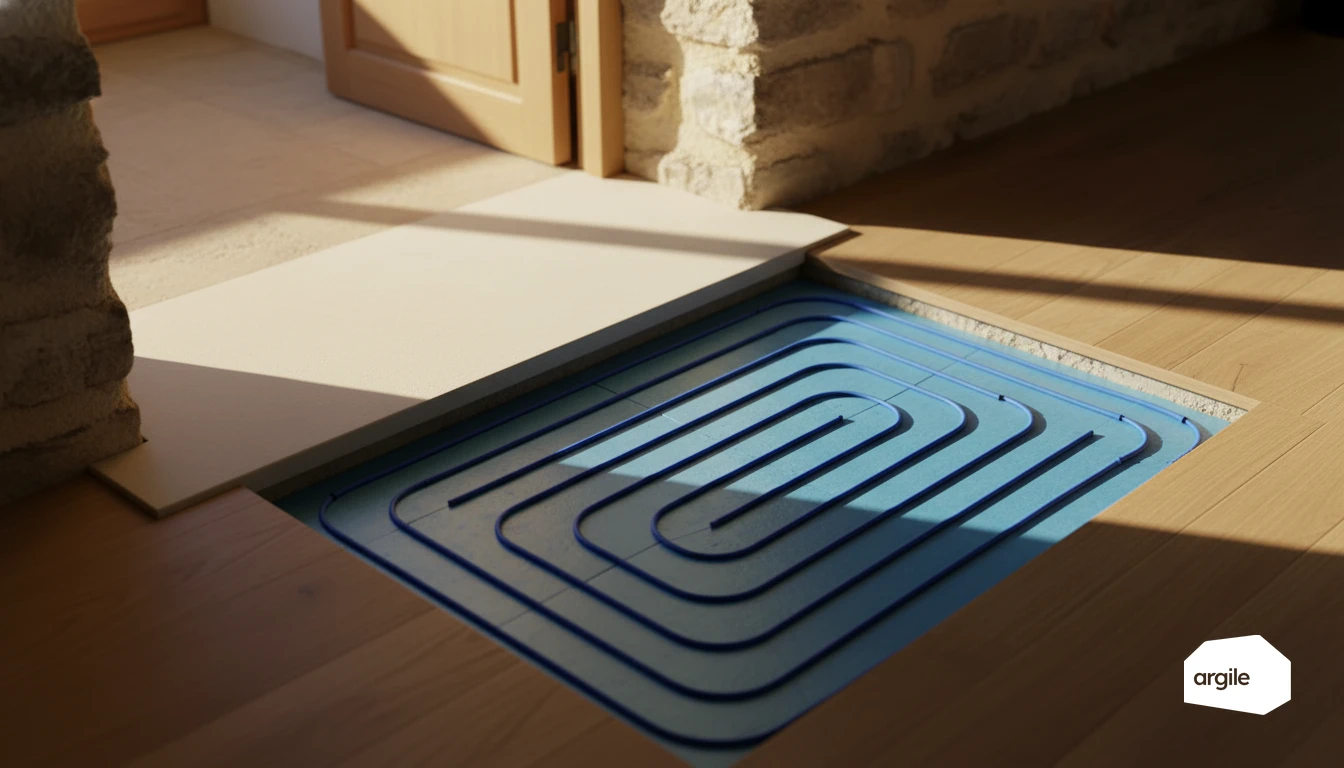
No text prescribes a spacing. Spacing is the adjustment variable between the output to deliver, the flow temperature you accept and the surface evenness you get. Approved systems publish output charts per spacing, and those charts are what govern on site, not a general rule.
| Lever | What it changes | What frames it |
|---|---|---|
| Tighter spacing | More output per m² at the same flow, more even surface | Output charts of the approved system |
| Wider spacing | Less pipe, but flow temperature raised for the same output | The cap on the finished floor |
| Active area won back | Output gained without touching temperature | Pipe layout, no-heat zones under fixed furniture |
| Reinforced perimeter zone | Corrects localised loss at façades and glazed bays | Room-by-room calculation, never a rule of thumb |
Loop length is derived, not copied
The maximum lengths circulating on forums are not traceable to any publicly accessible enforceable source. What is calculable is the full chain: loop output, the flow-return difference adopted, the resulting flow rate, the pipe's pressure loss, compared with the pump head available. The only ceiling that binds you is the one in the system instructions. On a single manifold, keep lengths close to each other, otherwise balancing becomes a permanent negotiation and you will pay for it in callbacks.
Screed cover thicknesses, on the other hand, are written down
| Type of floor | Minimum cover above the pipe | Above the stud | Insulation grades covered |
|---|---|---|---|
| Type A and reversible floor | 30 mm at any point | 25 mm at any point | SC1a, SC1b, SC2a |
| Type C | 20 mm at any point | Not applicable | SC1a Ch, SC1b Ch |
| Electric radiant floor, for reference | 40 mm on SC1, 45 mm on SC2a | Not applicable | SC1, SC2a |
Screed cover is capped at 8 cm at any point. Source: CSTB, guide 3578_V4, table 5, figures repeated in the UNECP-FFB and CAPEB professional rules for flowing screeds of July 2022. In its E.04 sheet the AQC documents cracking on cover reduced to 15 mm, which is exactly the kind of dimension you check on site before the pour, and photograph.
Generator compatibility: what the floor imposes on the machine
A low-temperature emitter does not rescue an oversized heat pump
Underfloor heating is a heat pump's best ally because it accepts a low flow temperature. It does not compensate for a machine whose minimum modulated output exceeds the mid-season demand. Generator sizing is a separate exercise, done on heat loss and not on floor area: that is the subject of our article on the air-to-water heat pump and underfloor heating pairing from the sizing side.
Manifolds, flow meters and controls
At the manifold, flow meters carry the balancing and the actuators carry the zone control. Specify a pump chosen on the network's real pressure loss rather than a catalogue, a careful purge, and settings that are written down. An oversized pump hides poor balancing right up to the day it produces noise and lukewarm returns.
The reversible case changes the rules
If the system also has to provide cooling, you are no longer in the same reference framework. Minimum flow water temperatures, the safety cut-out and the limits on the covering's thermal resistance are all tighter, and they are written in CSTB technical guide 3164. Look at what cooling mode actually imposes before you sell it.
Pre-pour checks and heat-up: what gets recorded
The pressure test
The AQC's CH-PC commissioning test sheet sets the test pressure at twice the working pressure, with a minimum of 6 bar, before and during the pour. The hold time is not given by any publicly accessible source, it comes from the system instructions: take it from there and write it on the report. After any pipe repair, a fresh test is due.
First heat-up
| Step | Rule | Source |
|---|---|---|
| Pressure test | Twice working pressure, minimum 6 bar, before and during the pour | AQC, CH-PC commissioning test sheet |
| Start-up on calcium sulphate flowing screed | Possible from the 7th day after pouring | CSTB, guide 3578_V4 |
| Temperature rise | In 5°C steps | AQC, CH-PC commissioning test sheet |
| Around the floor covering installation | Heating off at least 2 days before and 2 days after, grouting included | UNECP-FFB and CAPEB professional rules for flowing screeds, July 2022 |
| Exemption from first heat-up | Type C floors and decoupled bedded installation | CSTB, guide 3578_V4 |
What you hand over at completion
The recorded pipe layout with loop lengths, the pressure test report, the record of the heat-up steps, the residual moisture readings taken before the covering went down, and the manifold settings sheet. Moisture readings are taken with the carbide bomb method, with at least two samples per room under 100 m² then one per additional 100 m² (CSTB, guide 3578_V4). This file is not paperwork: it is what separates the liabilities when a wood floor lifts two winters later. Hand the heating curve over with it and you avoid half the first-season calls.