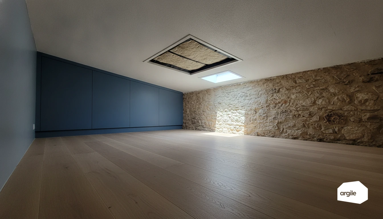
A loft hatch is judged on its U-value, and that value follows from the thermal resistance of the panel: excluding surface resistances, U is the inverse of R. A bare plywood panel sits around R 0.5, so U 2, while the French BAR-EN-101 grant sheet requires R ≥ 7 m².K/W in cold lofts to earn certificates, which is U 0.14. The same square metre therefore passes roughly fourteen times more heat at the hatch than elsewhere in the ceiling. That said, the hatch covers very little area: it is the air leak around it, not the panel on its own, that does most of the damage.
Why the loft hatch drags down insulation performance
Thermal bridge: a small area, big heat losses
In the loft, the insulation must form a continuous layer. The hatch breaks this continuity. Its frame, its fixings and a panel that's too thin create a thermal bridge. The result is localised heat escape, like a missing roof tile. The hatch is one of the parts of that wall we name one by one on a roof-space section (in French), with the ceiling, the vapour barrier and the blown insulation.
Air leaks: when loft airtightness is broken
A poorly closing hatch lets air through. These air leaks defeat the insulation, because warm air rises and escapes into the loft. Draughts, dust, discomfort and excess consumption appear, even if the insulation thickness is adequate.
Condensation and moisture: risks for the insulation and the roof structure
When humid indoor air infiltrates and then meets a cold area around the hatch, condensation can form. The result is insulation that settles or degrades, and timber more exposed to mould. Careful airtightness work limits these risks.
The U-value of a hatch: the conversion, and what it does not tell you
Thermal resistance is read off the product sheet, the U-value follows from it. Excluding surface resistances the relationship is direct and can be done in your head during the survey.
| Thermal resistance of the panel, R in m².K/W | Corresponding U-value, in W/(m².K) | What that looks like in practice |
|---|---|---|
| 0.5 | 2.00 | bare timber panel, the most common case in existing homes |
| 1 | 1.00 | panel with a thin insulation layer added |
| 2 | 0.50 | roughly insulated hatch |
| 4 | 0.25 | entry-level off-the-shelf insulated hatch |
| 6 | 0.17 | the level required in roof slopes by the BAR-EN-101 sheet |
| 7 | 0.14 | the level required in cold lofts by the BAR-EN-101 sheet |
Two limits to keep in mind before putting this table in front of a client. First, surface resistances are not counted here, so the real U-value of the element is slightly more favourable than the figure shown. Second, and more important, the area ratio: a hatch takes up a tiny fraction of the ceiling, so its U-value gap never turns into a visible difference on the bill on its own.
Why the real defect is the frame, not the panel
This is why a client who bought an insulated hatch still complains about draughts. An element conducts, a leak transports, and the air flow appears on no product sheet. An interrupted perimeter seal, a catch that does not compress, a vapour barrier stapled instead of bonded to the frame, and warm indoor air runs into the loft carrying the moisture it holds. The panel merely conducts a little faster than the rest of the ceiling. So work in this order: continuity of the air barrier all the way round, then compression of the seal, then the thermal resistance of the panel.
Diagnosing a poorly insulated loft hatch on site
Unmistakable signs: draughts, dust, moisture marks
On site, a hatch that lets air through is often spotted without any instrument. Draughts at the ceiling, a sensation of a cold spot, complaints of discomfort in winter. In the loft, you sometimes see a film of dust "drawing" the leaks around the frame. Another warning sign: rings, droplets or early mould. This is common when warm indoor air meets a colder zone.
Simple airtightness check: smoke, torch, feel under pressure/negative pressure
To confirm, a smoke pencil, an incense stick or a little smoke lets you visualise air movement. Work with windows closed, then create slight negative pressure (extractor hood or mechanical ventilation) and observe. A torch on the loft side, with a dark room on the inside, helps spot gaps. A quick test, but very convincing for the client. To go further, infrared thermography also lets you visualise thermal leaks and airtightness defects.
Measuring and recording: dimensions, flatness, condition of the frame and support
Record length, width, thickness, and above all the gaps around the perimeter. Check the flatness of the panel and frame, the condition of the seals, hinges and locking mechanism. Look at the support (ceiling, opening, vapour barrier) to avoid patching "onto something loose." Clean measurements, backed by photos, give you a solid basis for quoting. From the measurements taken on site, the AI extracts areas, heights and dimensions to feed the 2D plan and the costing.
Choosing the right insulation and airtightness solution for the loft hatch
Off-the-shelf insulated hatch or custom solution: selection criteria
If the loft access is used often, an off-the-shelf insulated hatch saves time. Look at the insulation thickness, the quality of the seal, and the closing system that properly compresses the frame for airtightness. A custom solution becomes worthwhile if the opening is non-standard, if the frame is deformed, or if you're trying to limit thermal bridges at the opening surround.
Materials and insulation levels: insulating panel, seals, vapour barrier on the loft side
To insulate the hatch, PIR panels or mineral wool are common choices, with thermal resistance consistent with that of the ceiling. The seal must be continuous, compressible, and fitted on a clean support. Where a vapour barrier is present, the goal is continuity. Connect the membrane to the frame and treat air pathways on the loft side to maintain a continuous vapour barrier.
Special cases: hatch on a plasterboard ceiling, wooden hatch, reduced or offset access
On a plasterboard ceiling, reinforce the perimeter and avoid screwing into the void. On a wooden hatch, plan for a locking mechanism that seats firmly, since wood moves. If access is reduced or offset in the loft, a hatch with offset hinges or a raised frame can simplify handling without sacrificing airtightness.
Achieving an effective installation: key steps for a truly airtight loft hatch
Preparing the support: rigid frame, clean surface, correcting defects
Before closing up your loft, aim for a clean, stable support. Check squareness and flatness, then fit a rigid, well-anchored frame (screws, brackets). Remove dust and grease. Fill gaps and cracks with acrylic sealant or mortar, depending on the substrate. A sound base avoids rework and guarantees even compression of the seal.
Ensuring airtightness continuity: perimeter seals, compression, closing mechanisms
Fit a continuous perimeter seal (EPDM foam or suitable neutral-cure silicone) on the frame. The key point is pressure. Favour closing mechanisms that press the panel firmly (latches, turn buckles) rather than a simple hook. Check there are no hard spots. A thread of air is a leak that turns into a parasitic draught.
Ensuring insulation continuity: connections with the loft insulation and treatment of junctions
Treat the hatch like a small insulated wall element. Insulate the panel without compressing the insulation, then connect it to the loft insulation blanket all the way round. At the junctions, use a vapour-barrier-compatible tape or an applied membrane, to avoid the thermal bridge and condensation.
Checks and requirements in 2026: securing the quality and compliance of your loft works
End-of-job checks: local airtightness test, thermography, visual inspection
In the loft, a clean end of job comes down to three actions. A local airtightness test around the hatch, connections and penetrations (smoke or a simple measurement) spots air leaks. Thermography, with a sufficient temperature difference, reveals thermal bridges and settled areas. Finish with a visual check of insulation continuity, of the vapour barrier where planned, and of sensitive points near ducts and downlights.
Points of attention for aid schemes (MaPrimeRénov', CEE): traceability and loft photos
For MaPrimeRénov' and CEE, the key is traceability. The detailed invoice, exact references, treated area and stated performance must be consistent with the reality on site. Keep dated photos of the loft before, during and after, and archive the requested documents (certificate, technical data sheet, proof of qualification) to respond quickly in the event of an inspection.
RGE good practices: product data sheets, proof of installation, informing the client about hatch use
On the RGE side, put together a simple RGE file. Product data sheets (CE marking, ACERMI or equivalent), installation diagrams, thickness reference marks, and photos of critical points. Also inform the client. A hatch must remain accessible, airtight, and handled without compressing the insulation. It's the small access point that prevents large heat losses.