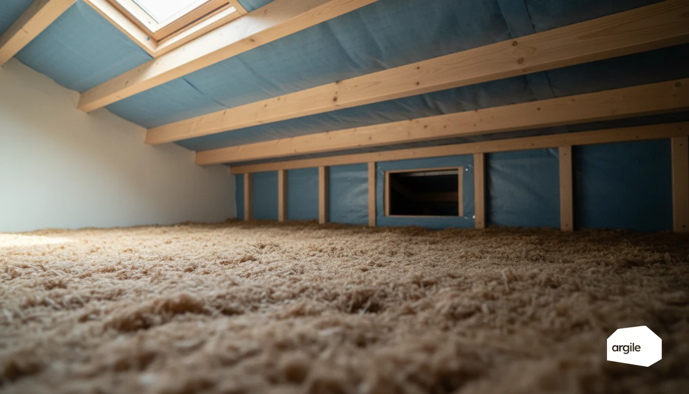
A loft conversion does not win floor area, the insulation takes some of it back first. At rafter level, an upgraded roof is held to 0.16 W/m².K under Table 4.3 of Approved Document L, which at λ 0.035 means around 210 mm of insulation, close to 230 mm off the slope once counter-battens and plasterboard are on. Approved Document L concedes the point itself: note 3 to that table allows a lesser standard where meeting it would limit headroom, provided the insulation plus any required air gap fills the rafter depth and the lowest practicable U-value is achieved. So the insulation depth is what decides the room you can promise, and that call belongs at survey stage, before the quote.
What decides the floor area you can promise
Headroom, usable area and the Part K stair rule
The square metres on your sketch are not the square metres the client will live in. Two constraints bite. The first is the stair: Approved Document K asks for 2 m of headroom over a flight, relaxed on loft conversions to 1.9 m at the centre of the stair width falling to 1.8 m at the side. The second is the slope itself, where usable area runs out well before the ceiling meets the floor. On a loft, the line where the room stops being usable shifts by tens of centimetres depending on the insulation depth, and it is that shift you have to price before promising a bedroom.
What the survey has to bring back
Three dimensions frame the job: ridge height measured to the underside of the structure, roof pitch, and rafter spacing and section. They give the position of the usable line before insulation, then after, once the depth is settled. Add the condition of the ceiling joists and the type of structure, trussed or cut roof, which decides whether there is a project at all. Argile's AI pulls heights, pitches and areas from surveys taken on site and feeds the 2D plan.
Trussed rafters: the point that stops half of these jobs
A W-truss roof cannot be opened up without structural work: the ties and diagonals carry the stability, and cutting them without a design is putting your liability on a roof. The remedial design comes from an engineer, with trimmers, a support beam and loads carried back to the load-bearing walls. That item changes the order of magnitude of the job, and it is settled before anyone talks about insulation.
The limits and the thickness that goes with them
Two tables, and which one applies depends on the element
Approved Document L holds new and retained elements to different figures, and a loft conversion routinely involves both.
| Element | Limiting U-value | Where it comes from |
|---|---|---|
| New fabric element in an existing dwelling, roof | 0.15 W/m².K | Table 4.2 |
| Retained roof, threshold above which it must be upgraded | 0.35 W/m².K | Table 4.3, column (a) |
| Retained roof, improved standard | 0.16 W/m².K | Table 4.3, column (b) |
| Retained wall, internal or external insulation, improved | 0.30 W/m².K | Table 4.3, column (b) |
Paragraph 4.13 adds the escape route: where the improved value is not technically or functionally feasible, or would not achieve a simple payback of 15 years or less, the element is upgraded to the lowest U-value that is feasible and does pay back within 15 years.
The thickness is calculated, not chosen
Insulation depth follows from the declared lambda, by thickness equals R multiplied by λ. The table gives what has to go in for each of the two insulation-only resistances a pitched roof typically needs.
| Declared lambda | Thickness for R = 6 | Thickness for R = 7 |
|---|---|---|
| 0.030 W/m·K | 180 mm | 210 mm |
| 0.032 W/m·K | 192 mm | 224 mm |
| 0.035 W/m·K | 210 mm | 245 mm |
| 0.038 W/m·K | 228 mm | 266 mm |
| 0.040 W/m·K | 240 mm | 280 mm |
At rafter level these depths almost always go in as two crossed layers, one between the rafters and one below them, which handles continuity and avoids hand-trimmed pieces. The configurations are set out in our article on insulating at rafter level in converted lofts.
What the depth takes, in centimetres and in square metres
An 80 mm rafter will not hold 210 mm of insulation. The second layer runs below the rafters, counter-battens and 12.5 mm of plasterboard go on, and the finished slope ends up between 200 and 260 mm below the structure. On a 40 degree pitch, 230 mm measured perpendicular moves the usable line inward by about 36 cm on each side, since the horizontal shift is the depth divided by the sine of the pitch. Over 8 metres of loft length, the two slopes together take close to 6 m², before anyone mentions the stair. That is the calculation that belongs on the quote, not a footprint area.
The trade-offs that give the space back
Insulating over the rafters: paying for the roof to keep the volume
Insulating above the rafters leaves the whole internal volume available and removes the cuts between rafters, and with them the continuity defects. Against that, the covering has to come off, verges, eaves and flashings have to be reworked and the overhangs extended. The extra cost is weighed against the square metres recovered: above a certain local value per square metre it becomes the economically rational option, and that is a calculation, not a technical preference.
Low lambda against budget: where the premium earns its place
Going from λ 0.040 to λ 0.032 saves 48 mm of depth at equal performance, close to 8 cm of usable width at the eaves across both slopes. The product premium is weighed against the value of the square metres recovered, exactly as with insulating over the rafters, and the answer leans towards the low lambda in lofts with limited ridge height, where every centimetre changes the brief.
Junctions: where the calculated performance goes
Loft hatch, eaves, wall-to-roof junction, purlins and service penetrations are the places where insulation stops and airtightness continuity breaks. They do not show on a drawing and they do show in the measurement. Their weight is counted in linear heat loss: see the junction thermal bridges modelled in the French energy assessment.
What protects the job and the file
Structure, ventilation and daylight: the three checks that come first
The floor is checked against reality, joist section, spacing, bearings, condition of the timber and deflection, with a calculation where there is any doubt. Roof ventilation is designed in from the start, not added afterwards: an insulated, sealed loft with no ventilation path produces condensation under the covering within one winter. Daylight comes from roof windows, whose thermal performance and shading also govern summer comfort, as our article on the thermal performance of roof windows sets out.
Permissions and fire: what a third storey changes
Many loft conversions fall within permitted development, subject to the volume allowances in Class B of Schedule 2 to the General Permitted Development Order, but that says nothing about the Building Regulations, which apply either way. The item most often underestimated is fire: turning a two-storey house into a three-storey one brings Approved Document B into play, with a protected stairway, fire doors to habitable rooms and an escape route that has to be designed rather than assumed. That work is priced at the same time as the insulation, or it appears as a variation.
The compliance file: what has to be readable
Three entries decide whether the work signs off.
- The insulated area in square metres, consistent with the survey and with the area quoted to the client.
- The U-value achieved, written explicitly, with the calculation and the product's declared lambda behind it.
- The element treated, new or retained, since that is what fixes the limit at 0.15 or 0.16.
Argile brings public grants, energy scheme funding and monthly payments into one funding plan, so the client sees the net cost before signing. The rejection reasons that come up most often, and how to head them off, are covered in our article on rejected retrofit grant applications.