Understanding thermal bridges in the building envelope
Simple definition and common types (linear, point)
Thermal bridges are areas where insulation is interrupted or less effective. Heat passes through faster there, as if the envelope had a poorly closed seam. There are mainly linear thermal bridges, at junctions (wall-floor, wall-roof, window reveals), and point thermal bridges, linked to fixings or penetrating elements.
Why the envelope creates heat loss at these points
These points appear when conductive materials touch, when the insulation is poorly connected, or when the geometry multiplies angles. As a result, the heat flow concentrates locally. Even with good thermal resistance on the walls, a poorly treated junction can become a real energy leak.
Site impacts: discomfort, condensation, rising bills
On site, this shows up as cold walls, felt drafts and sometimes condensation. When moisture settles in, the risk of mould increases, especially around joinery. In the end, the boiler or heat pump compensates more often, and consumption follows the same trend. For more on this topic, see our article on linear heat loss from thermal bridges.
Spotting risk areas on site to limit heat loss
Sensitive junctions: floor/wall, wall/roof, window reveals
On site, losses mainly slip through the junctions. The floor/wall pair, the wall/roof connection and window reveals often concentrate thermal bridges. Check insulation continuity, thermal break treatment, and the sealing of membranes and tapes. A small gap there is like a lamp left on outside.
Visible clues: mould, cold marks, cracks, feeling of a cold wall
- Mould in corners, around windows, or at the base of walls.
- Dark marks, stains, or areas that stay damp after ventilating.
- Cracks at junctions, or joinery joints that move.
- Feeling of a cold wall and localized drafts, even with heating running.
Useful diagnostic methods in 2026: thermal camera, airtightness testing, energy audit
The thermal camera helps visualize the differences, ideally in winter with a good temperature gap. Blower-door testing locates air leaks to treat before finishing. The energy audit, meanwhile, frames priorities and secures the work plan when several trades overlap.
Treating thermal bridges: insulation solutions suited to each configuration
External insulation: insulation continuity and managing singular points
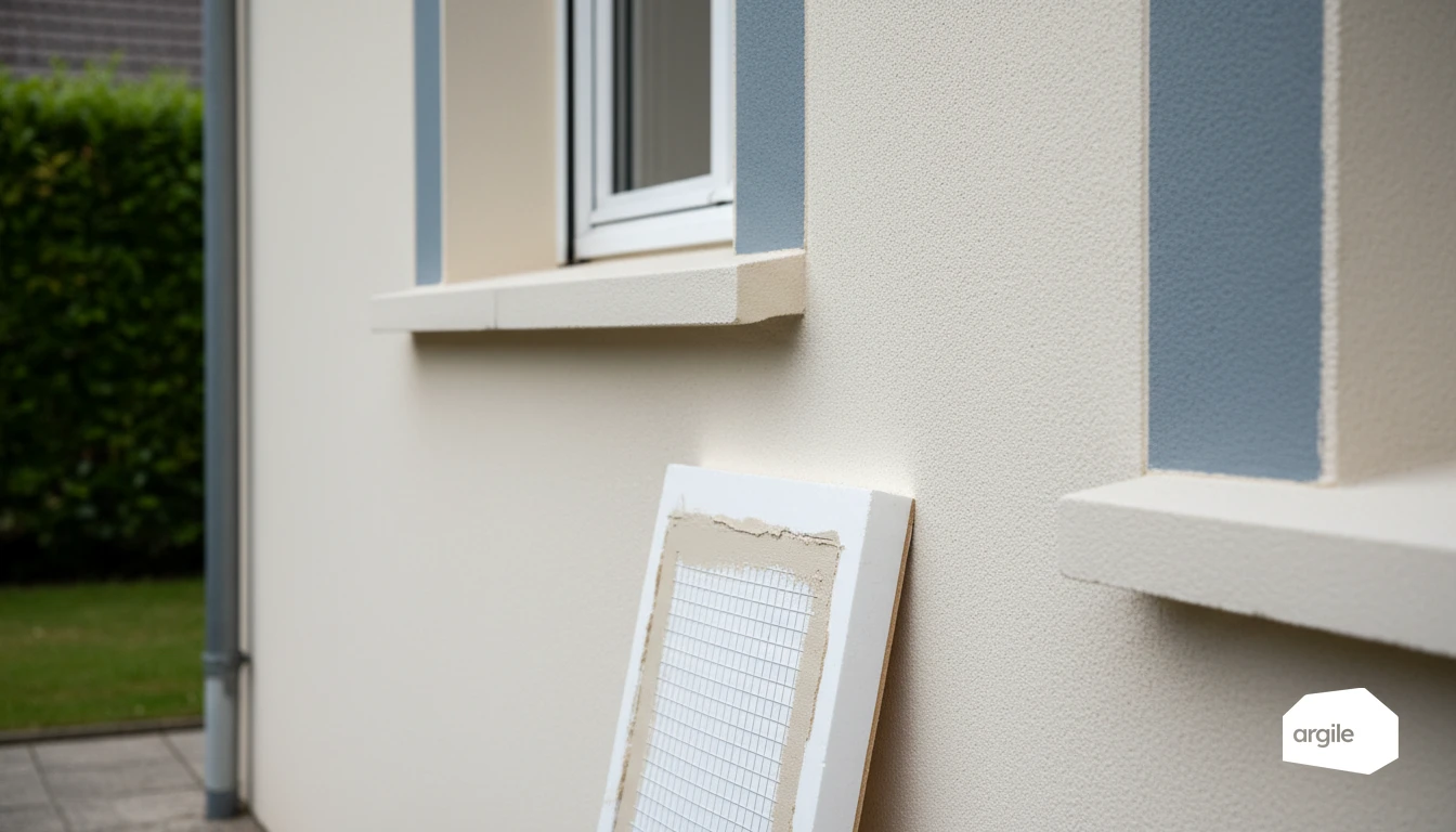
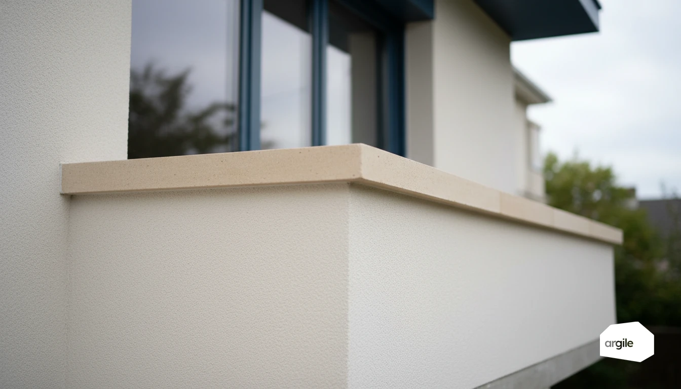
With ITE, the most effective approach is to aim for insulation continuity across the whole envelope. Thermal bridges concentrate at slab edges, balconies, wall-roof junctions, and around openings. Plan for insulation returns at the edges, dedicated accessories for sills and lintels, and a layout that limits cuts and breaks. To cost these areas without guesswork, façade take-offs and the choice of insulation are handled down to the square metre.
Internal insulation: thermal breaks, insulation returns, treating the reveals
With ITI, thermal bridges often come back to intermediate floors, partition walls, and window reveals. Work with suitable thermal breaks where possible, and take care with the insulation return over 20 to 40 cm in the embrasures and at wall-ceiling junctions. A continuous airtightness membrane helps maintain real performance.
Joinery and airtightness: installation, sealing, sills and connections
A high-performance window quickly loses its gains if the installation creates thermal bridges. Aim for careful installation within the insulation plane, with sealing using tapes, compression sealing tape or compatible sealants, and an insulated sill or thermal break. Connect the joints to the air barrier, treat the roller shutter boxes, and check with a blower-door test if the job site includes one. To choose the most suitable solution, see the differences between face-fixed, tunnel and rebate installation. Upstream, windows and doors are picked out on the façades and listed for the costing.
Thermal bridges and best practices: points to watch to avoid rework
Choosing the right materials and accessories (thermal breaks, reveal linings, membranes)
Thermal bridges often arise at junctions. In both ITI and ITE, treat the reveals, slab edges, and the roof-wall junction first. Choose thermal breaks compatible with the substrate, reveal linings suited to the insulation thickness, and membranes specified by the system's technical approval. A poorly chosen accessory quickly costs you at the finishing stage.
Coordinating trades: masonry, framing, joinery, insulation
Most rework comes from trade interfaces. Plan layouts together and decide who does what. Fitting joinery, reveal linings, insulation returns, tapes and sealant. Set clear stop points and a clear order of operations. A photo of each zone before closing up avoids surprises.
Quality checks: continuity, fixings, airtightness and finishes
Before closing up, do a simple visual check. Insulation continuity, compliant fixings, airtightness around penetrations and joinery, and finishes at the corners. For more on this topic, also see connection thermal bridges.
- Membrane overlaps and bonding.
- No gaps around the frames, suitable sealant.
- Treatment of service penetrations.