Insulation continuity decides the real performance of an envelope far more than the thickness installed: 1% of area left uninsulated adds around 10% of heat loss, and 5% adds 30%. The breaks always sit in the same places, wall-floor and wall-roof junctions, cross-walls, window reveals, sills, shutter boxes, hatches and service penetrations, and more still at the interface between two trades or between the existing building and an extension. The junction is planned before installation, by deciding where the airtightness plane runs and how far the insulation is carried onto each return. The check that counts is post-works thermography, and a break found at that stage costs the dismantling of the finish.
Understanding insulation continuity in the building envelope
What continuity really covers: thermal, airtightness and vapour control
Continuous insulation is not just about "putting insulation everywhere." It means keeping the same barrier without a break across the whole envelope, and completing it with good airtightness. The vapour barrier or vapour-retarder, on the warm side, helps control water vapour transfer, provided the overlaps and joints are done carefully.
Thermal bridges: where they hide most often (junctions, penetrations, interfaces)
Thermal bridges are mostly found at floor-wall junctions, wall-roof junctions, party walls, window reveals, sills, and shutter boxes. They also appear at penetrations, ducts, spotlights, hatches, and at interfaces between trades, for example interior insulation and window frames, or exterior insulation and balconies. One poorly connected detail is enough to create a local cold spot. To go further on these connection details, see also the junction details in renovation.
Why a continuous envelope changes everything: comfort, humidity, consumption
When the envelope is continuous, the walls stay warmer, comfort improves, and temperature swings settle down. The risk of condensation and mould is reduced, while ventilation becomes more effective. In the end, the house "leaks" less, and energy consumption drops, provided the installation is checked, for example with an air leakage test.
Treating sensitive areas for insulation without breaks
Wall/floor, wall/roof and party-wall junctions: the details that make the performance
The performance of insulation is often decided at the junctions. Where wall, floor and roof meet, a lack of continuity creates thermal bridges, hence cold walls and sometimes condensation. Aim for a continuous layer of insulation, with returns on party walls and treated junctions, and plan from the design stage where the airtightness line runs.
Window frames, shutter boxes, sills: sealing and insulation connections
Around windows, the right approach is to combine sealing with an insulation connection. Treat the reveal, the frame and the sill with suitable tapes, then bring the insulation as close as possible to limit air leaks. Shutter boxes should be treated like a small wall section. If air gets through, heat follows. Ensure continuous connections that remain accessible for maintenance.
Service penetrations and ducts: guaranteeing airtightness without improvisation
Every duct is a risk for airtightness. Use sleeves or grommets designed for penetrations, and sealed boxes for electrical fittings. Avoid using foam alone as a "patch." It shrinks and ages poorly. A check at the end of the project, or even an air leakage test where relevant, secures the result. To go further on this point, see sealed boxes for electrical outlets.
Choosing the right insulation systems for the project (internal, external, loft)
Internal wall insulation: continuity behind the linings and managing water vapour
With internal insulation, the right system is one that stays continuous behind the linings, at wall-floor junctions and around window frames. Treat outlets, boxes and ducts to limit thermal bridges. On the humidity side, a membrane or vapour-retarder suited to the substrate and climate prevents condensation within the wall.
External wall insulation: connections at the base of the façade, reveals, roof overhangs
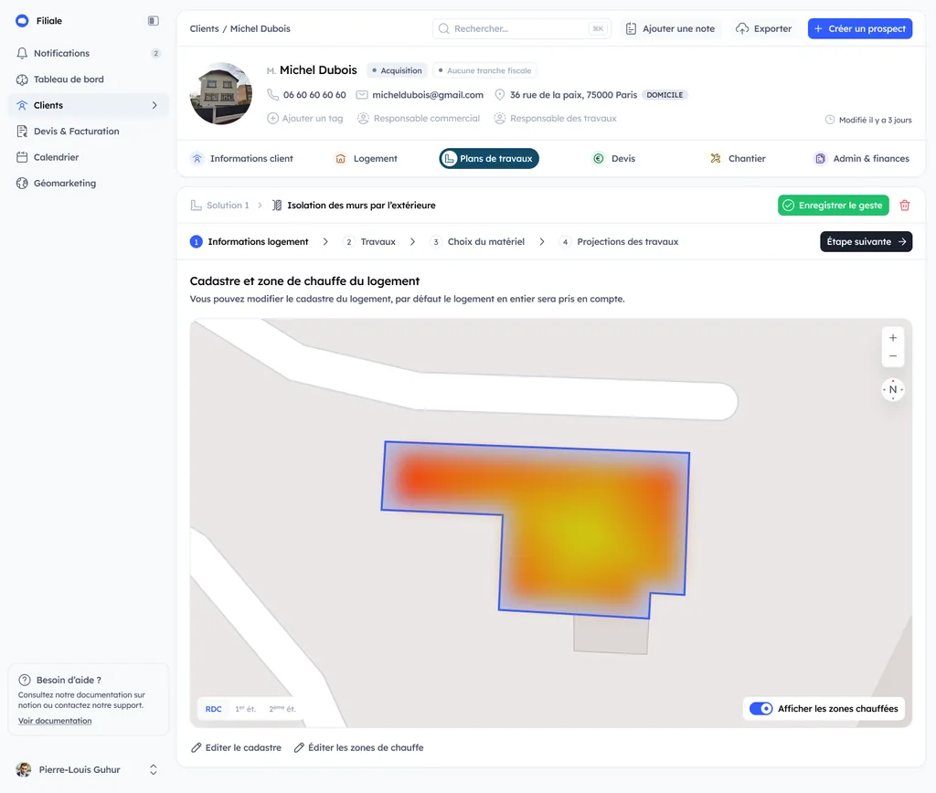
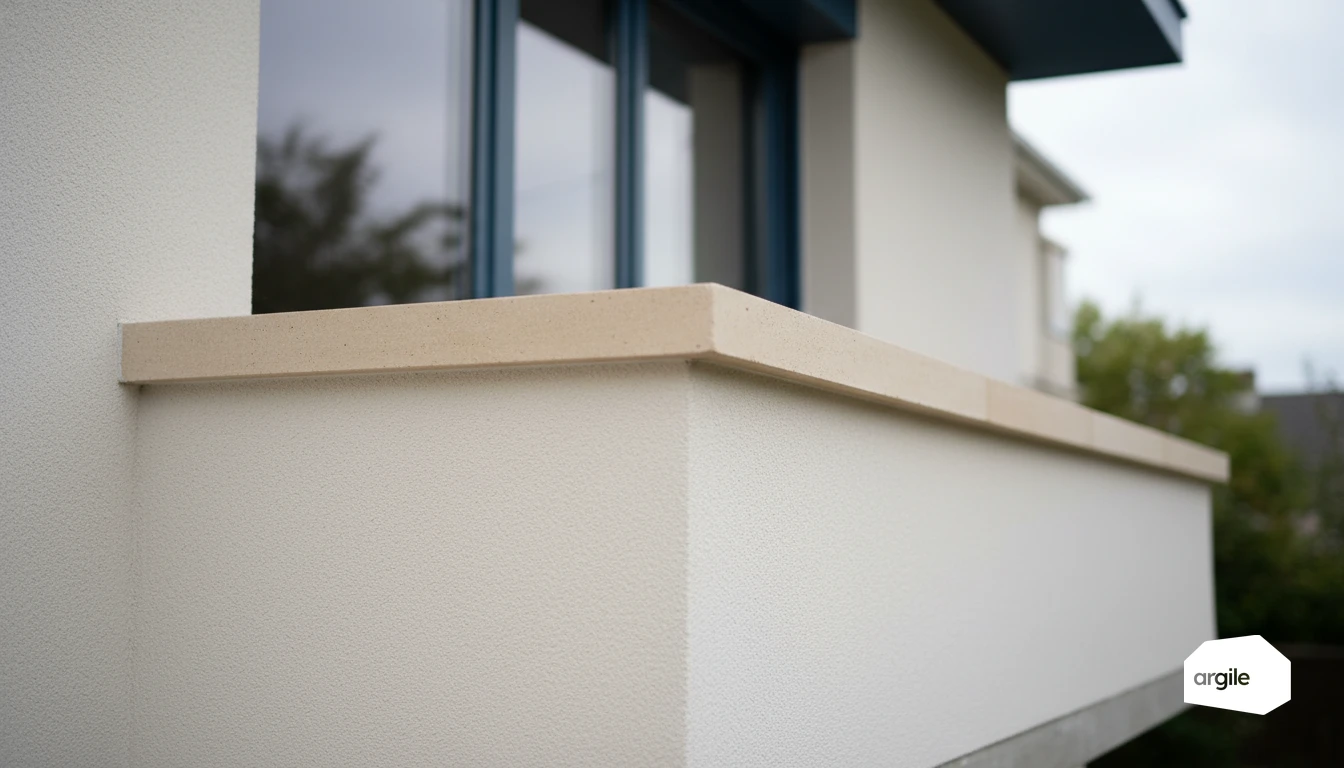
With external insulation, performance is decided by the details. Pay close attention to the base of the façade, protection against water splashes, and continuity with the foundation wall. In the reveals, keep a thickness compatible with the openings. Under roof overhangs, plan the alignment ahead of time to preserve airtightness and avoid insulation returns that get "cut into a corner." On this kind of job, façade measurements, opening detection and the choice of insulation and finish go from survey to quote with no re-entry.
Roofs and lofts: rafters, hatches, recessed spotlights and special points
In lofts, favour continuous insulation on the floor or along the rafters, without compression. Hatches must be insulated and sealed. For recessed spotlights, plan for compatible protective covers to avoid overheating and air leaks. Also treat gables, valleys, ducts and mechanical ventilation. This is where kilowatt-hours escape. To go further, see also blown-in loft insulation.
Implementing and checking continuity: your on-site checkpoints
Before closing up: continuity checklist (tapes, adhesives, membranes, patches)
Before installing the cladding, check the continuity of airtightness around the insulation. Substrates should be dry and dust-free, primed if required. Overlaps compliant, corners treated, connections at windows, slabs and party walls. Every penetration (ducts, drains, boxes) must be sleeved or patched with a compatible tape and adhesive. Keep photos, they are your record of the project.
Tests and checks: smoke test, thermal camera, air leakage testing where possible
A smoke pencil or smoke test quickly reveals leaks around junctions. The thermal camera is useful when the temperature difference is sufficient, to spot defects and thermal bridges. When possible, schedule an air leakage test during the project (before finishing), then again at project completion, with a qualified operator.
Coordinating trades: avoiding damage between work packages
Continuity is mostly won through coordination. Share a penetration plan and enforce a simple rule. Every perforation is immediately sealed with the right system. Protect the membranes, set up a checkpoint at each change of trade, and keep a repair kit on site. Those checkpoints hold better when the site is planned and tracked from the client record, with photos and snag clearing.
In 2026: insulation continuity, quality of execution and grant expectations
Registration and proof of proper installation: photos, technical data sheets, self-checks
On site, the difference is often decided by the details. For insulation, keep a clear record of what has been installed. Take photos before closing up, keep the technical data sheets, and note your self-check points. A few simple pieces of evidence avoid a lot of discussion in the event of an audit.
Funding: securing the file with consistent execution details
The grant schemes look at the consistency between the quote, the invoice and what was actually done on site. Same product, same thicknesses, same areas, same declared resistances. If you change a reference, formalise the amendment and attach the product data sheet. A well-aligned file saves time for both you and the client.
Energy audit and work scenarios: envelope continuity as the common thread
The audit often highlights a logical sequence. Treat the envelope first. Then the systems. Track down thermal bridges, airtightness, and the associated ventilation. Unbroken continuity stabilises performance and limits unpleasant surprises.