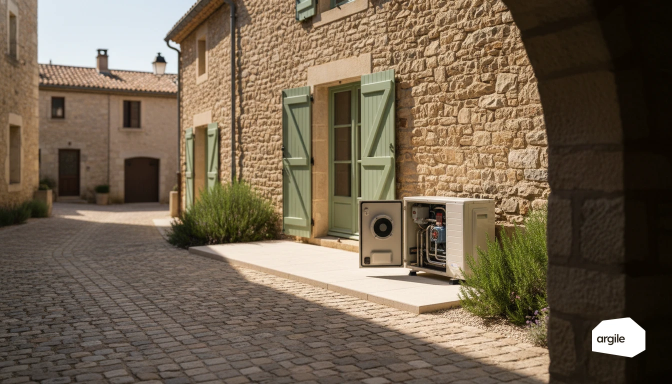
The expansion valve drops the pressure of the refrigerant leaving the condenser and meters the feed to the evaporator, which sets the superheat at the suction line. No text publishes a universal superheat range: the target comes from the manual for the model fitted, and what you can defend in a dispute is the reading taken at steady state, not a figure found online. The work itself, though, is regulated: Article R543-79 of the French environment code requires a leak check above 5 tonnes of CO2 equivalent and on every modification affecting the circuit, at intervals set by Article 4 of the order of 29 February 2016.
What the expansion valve regulates, and what gets measured
Pressure, flow and superheat: the function in one line
The expansion valve is the restriction in the circuit. It drops the pressure of the liquid leaving the condenser and sets the flow admitted to the evaporator, so that the refrigerant is fully vaporised and slightly superheated at the compressor inlet. Too far open and liquid returns to the compressor. Too far closed and the evaporator is starved, output collapses, and the machine runs longer for the same demand.
The readings that settle it, and the order to take them in
When diagnosing, superheat and subcooling are read as a trend, on a stabilised machine. Before blaming the valve, secure the conditions: compliant air or water flow, clean filters, unfouled exchangers, open valves. Many drifts pinned on the expansion valve actually come from water-side flow or from unsuitable sizing, and adding refrigerant on that ground makes matters worse.
The symptoms to log on the intervention record
- Unstable flow temperature, short cycles, defrosts more frequent than the previous season.
- Abnormal frost on the exchanger or on the suction line while running.
- Hissing or clicking at the restriction, compressor current on the rise.
- Suction and discharge pressures outside the manufacturer's envelope at steady state, with outdoor conditions recorded.
These observations are better logged during the job than back at the office in the evening: the voice agent takes them down as you speak and fills in the file.
The valve types and what they change when diagnosing
Thermostatic valve: pressure balance on a bulb
The thermostatic valve sets flow through a balance between bulb pressure, evaporating pressure and spring tension. It targets a steady superheat at the evaporator outlet. It is robust, forgiving, and can be diagnosed without a configuration tool, which counts on a breakdown call. Its limits lie in how fast it responds when conditions swing, and in the risk of hunting if the bulb is poorly placed or poorly insulated.
Electronic valve: stepper control and configuration
The electronic valve drives a motorised orifice from pressure and temperature sensors, under the control of the controller. It holds superheat across a far wider range, which counts on a heavily modulating machine. On installation it demands compatible controls, careful wiring, compliant sensor positioning and configuration at commissioning. A recurring superheat fault on this type of valve is more often a sensor or upstream filtration problem than a valve problem.
Capillary tubes and fixed orifice designs: where you still meet them
A capillary tube is a fixed orifice with no regulation. You find it on simple or older machines, where cost dominates. It does not adapt the flow, so it is sensitive to charge, line length and temperature swings. On some reversible machines you also meet hybrid arrangements, a calibrated orifice paired with a solenoid valve depending on heating or cooling mode. Diagnosing them as if they were regulated valves leads to wrong conclusions.
What opening the circuit actually triggers
The leak check interval table
The interval depends neither on the machine output nor on the part replaced, but on the charge expressed in tonnes of CO2 equivalent. It is set identically by Article 5 of EU Regulation 2024/573 and by Article 4 of the French order of 29 February 2016.
| Equipment charge | Without leak detection | With a leak detection system |
|---|---|---|
| Under 5 t CO2e | No periodic check required | Not applicable |
| 5 to under 50 t CO2e | 12 months | 24 months |
| 50 to under 500 t CO2e | 6 months | 12 months |
| 500 t CO2e and above | 3 months | 6 months |
Two exemptions worth knowing before invoicing a pointless check. Hermetically sealed equipment labelled as such is out of scope below 10 tonnes of CO2 equivalent, and in residential buildings as soon as it holds less than 3 kg of fluorinated gas. To convert a charge in kilos into tonnes of CO2 equivalent, see refrigerant charge.
The real scope of the regime, routinely overstated
Article R543-75 of the French environment code lists four families and only four: CFCs, HCFCs, HFCs excluding HFOs, and PFCs. An R290 or R744 circuit falls outside that scope, so the leak check of Article R543-79 does not apply on account of the refrigerant. Certification, however, has stopped following that list: Implementing Regulation (EU) 2024/2215 extended it to natural refrigerants, and the French order of 21 November 2025 attaches hydrocarbons to categories A1 and A2 and carbon dioxide to a category B, both mandatory from 1 January 2027. Opening an R290 or R744 circuit therefore does call for a company certificate, whose exact scope is set out in the categories A1 to E. That takes nothing away from the safety requirements attached to flammability or pressure, nor from the manufacturer's warranty conditions, which remain contractual.
What gets logged, and for how long
The intervention record of Article R543-82 states the nature of the work, the refrigerant and the quantities recovered and added. Above 3 kg of HCFCs or 5 tonnes of CO2 equivalent of HFCs or PFCs, it is signed jointly by the operator and the equipment holder. Article R543-80 requires check records to be kept for five years. Below the thresholds no duty applies, but the record remains your only written proof of the circuit's condition at handover if a dispute arises. This follow-up is easier to keep unit by unit: in refrigeration engineer software, each installation keeps its refrigerant, its charge and its interventions, and the date of the next check can be read without opening the binders again.
Replacing an expansion valve without a second visit
The sequence for putting the circuit back in order
Recover the refrigerant before opening, replace the filter drier as a matter of course, braze under a nitrogen purge to avoid internal oxides, then run a pressure hold test and a vacuum pull-down with a rise check. Recharge by weight to the manufacturer's value, never by judging pressures. A circuit opened without a nitrogen purge produces oxides that block the new valve within weeks.
The checks before you leave site
Once stabilised, record superheat, subcooling, delta T at the emitters, currents and defrost behaviour, and compare them with the manual. Check the position and insulation of the sensor or bulb, a recurring cause of residual instability. Also check the outdoor sensor and heating curve: an over-aggressive setpoint reproduces the symptoms of a badly set expansion valve exactly.
What you tell the client and what stays in the file
For the client, one sentence is enough: the expansion valve meters refrigerant to the evaporator, and wrong metering makes the machine strain and multiplies its starts. In the file go the before and after readings, the part reference, the refrigerant quantity and the intervention record. On servicing duties and their check points, see heat pump servicing and, for tracking performance over time, how seasonal efficiency is calculated.