A thermal break connector is a load-bearing, insulating element slipped between a concrete slab and the facade (or between the facade and a balcony) to cut the continuous concrete path through which heat escapes. It is justified on two figures, and both are enforceable. Article 22 of the French order of 4 August 2021, which carries RE2020, caps the building's overall average linear thermal transmittance ratio at 0.33 W/(m² Sref.K) and the Ψ9 coefficient of junctions between intermediate floors and walls facing outside or an unheated space at 0.6 W/(m.K). RT 2012 set the overall ratio at 0.28 W/(m² SHONRT.K) under article 19 of the order of 26 October 2010, which is why two different figures still circulate on site. The Ψ you put in front of the design office is the one in the product's Technical Assessment, for the declared installation configuration, not a brochure value.
Thermal break connector: definition and principle
In concrete construction insulated from the inside, the norm in France, the internal lining stops at every floor while the slab runs through to the outer face of the wall: each slab edge becomes a cold line around the whole perimeter of the storey. The connector interrupts that path with an insulating body (polystyrene, rock wool or rigid foam) crossed only by the reinforcement that carries the loads, in stainless steel, roughly three times less conductive than the steel in reinforced concrete.
The floor connector runs along the slab edge; the balcony connector carries a cantilever and is sized like a structural member. With external wall insulation, the insulation passes in front of the slab edge and the floor connector usually becomes unnecessary; only the balcony still needs cutting.
Understanding thermal bridges and their impact on your jobs
Where thermal bridges hide: floor/wall junctions, load-bearing partitions, balconies, window reveals
Thermal bridges appear wherever the insulation is no longer continuous. They're often found at floor/wall junctions, at load-bearing partition walls, balcony slabs, and in window and door reveals. On site, a simple "offset" in the insulation, a poorly treated return, or an uninsulated window sill is enough to create a heat leak.
On-site consequences: heat loss, cold surfaces, condensation and mould
The result is heat loss that eats into actual performance, even with a good thickness of insulation. The affected areas become colder, which increases the risk of surface condensation, then mould. It's also a classic source of discomfort and client callbacks, because "it heats, but not everywhere".
New-build vs renovation: why thermal bridges aren't treated the same way
In new-build, you can plan ahead from the design stage with thermal break connectors, airtightness details and insulation continuity that's easier to guarantee. In renovation, you work with what's already there. Access to floor ends, balconies, and reveals often forces a choice between ITI and ITE, then careful millimetre-precise detailing at the junctions to avoid just moving the problem elsewhere. Before choosing, put a figure on what each thermal bridge costs in renovation in linear heat loss.
What the regulation caps, and what the design office needs from you
A connector is not a comfort extra, it is how you hold two ceilings that the thermal study will have to justify. RE2020 kept the mechanics of RT 2012, loosening the overall ratio and leaving the intermediate floor limit untouched.
| Thermal bridge requirement | RT 2012, order of 26 October 2010 art. 19 | RE2020, order of 4 August 2021 art. 22 |
|---|---|---|
| Overall average Ψ ratio for the building | ≤ 0.28 W/(m² SHONRT.K) | ≤ 0.33 W/(m² Sref.K) |
| Ψ9, intermediate floor to wall facing outside or an unheated space | ≤ 0.6 W/(m.K) | ≤ 0.6 W/(m.K) |
| Relief on written justification from the client | ratio raised to 0.5 W/(m² SHONRT.K) | not carried over |
The RT 2012 relief only opened on written justification establishing that no available technique could treat the thermal bridges of the ground or intermediate floors. It was never a way to rescue a botched layout.
The overall ratio is expressed per m² of Sref, the reference area, which is the living area for a dwelling. The Ψ9, for its part, plays out junction by junction, and it is what makes the connector compulsory in practice with internal insulation: the DPE 3CL method tabulates an intermediate floor / internally insulated wall junction at 0.92 W/(m.K), above the 0.6 allowed, while the same junction with external insulation drops to 0.13. These values describe existing buildings, but the order of magnitude is enough: concrete floors with internal lining do not pass the thermal study without a treatment covered by a Technical Assessment. To read these coefficients and their unit, see the linear thermal transmittance coefficient Ψ.
The values that count and when you hand them over
A connector's Ψ is a Technical Assessment value tied to one precise installation configuration, not a property of the product taken out of context. Hand it to the design office with the execution details before the thermal study is filed. Without those values the calculation switches to default coefficients, which are deliberately penalising, and the Bbio degrades without a single line of the job having changed.
Thermal break: when and why it's the most effective solution
What a thermal break connector is for: principle and expected gains
A thermal break connector is inserted into the slab-facade junction to cut thermal bridges through the concrete. It reduces heat loss and raises the surface temperature. The result is lasting comfort, less condensation and a more uniform envelope, especially at balconies and floors.
Types of thermal break connectors (floor, balcony, partition wall, ground floor) and their Ψ before/after
You choose based on the zone to be treated. Orders of magnitude below: "untreated" uses the DPE (3CL) tabulated values for an internally insulated wall where they exist, "with connector" the usual range found in Technical Assessments.
| Connector type | Where it goes | Make-up | Ψ untreated | Ψ with connector |
|---|---|---|---|---|
| Intermediate floor | slab edge, internally insulated wall | continuous insulation, stainless reinforcement | 0.92 W/(m.K) | 0.15-0.35 W/(m.K) |
| Balcony | cantilevered slab | insulating box, stainless bars, compression modules | 0.8-1.2 W/(m.K) | 0.1-0.3 W/(m.K) |
| Partition wall | partition / facade junction, internal insulation | vertical connector or insulating edge block | 0.82 W/(m.K) | 0.2-0.4 W/(m.K) |
| Ground floor | junction over a crawl space or basement | insulated slab edge, insulating infill blocks | 0.31-0.71 W/(m.K) | 0.1-0.3 W/(m.K) |
The parapet, on a flat roof, is treated with a dedicated connector or an insulation return on its inner face. Choose a product with a Technical Assessment and performance consistent with your insulation, without oversizing.
Floor thermal break: solid slab, precast slab or beam-and-block
On a solid slab cast in place, the connector is set at the edge before the reinforcement, its stainless bars lapping with those of the slab. On precast slabs, it is either factory-integrated or fitted at the edge on site. On beam-and-block floors, a connector at the beam end is combined with tongued insulating infill blocks. Before ordering, check in the Technical Assessment the scope of use in seismic zones, the fire resistance and the acoustic behaviour. The alternatives with internal lining are covered in the article on internal insulation and the intermediate floor thermal bridge. For a French site, the zoning and the works concerned are set out in our overview of seismic regulations in renovation.
Balcony thermal break: insulating box and reinforcement
A balcony thermal break connector is an insulating box crossed at the top by tensioned stainless bars (cantilever moment), by inclined bars (shear force) and at the bottom by compression modules. The model is chosen on the span, the loads and the railing: it is a structural calculation, not a catalogue pick. When the cantilever is too long, you switch to a balcony on brackets or a self-supporting one on posts, which only touches the facade at a few points.
Compatibilities to check: masonry, floor type, ITE/ITI and structural constraints
Before ordering, check the masonry (brick, concrete, block), the type of floor (pre-slab, beam-and-block, solid slab) and the continuity of ITE or ITI. Also check the loads, the reinforcement steel, fire resistance and acoustics. If in doubt, have it validated by the structural engineering firm, at the right time.
Installing a thermal break connector correctly in new-build: points to watch to avoid defects
Key installation steps: positioning, insulation continuity, treatment of floor ends
Precise positioning from the moment of installation. The thermal break connector must be level, with no gaps, and perfectly bonded to the wall or masonry. Ensure continuity with the facade or lining insulation. Otherwise, thermal bridges come back through the junctions.
- Treat the floor ends. No crushed insulation, no concrete "bridging" behind it.
- Respect the installation direction and the intended accessories. Corners and load-bearing partitions must be managed from the layout stage.
Details that make the difference: airtightness, resilient strips, alignment of reservations
Controlled air around the junctions. Redo the joints with compatible membranes or renders. Install resilient strips wherever specified to limit transmission. Check the alignment of reservations and rebar waiting bars. A misalignment costs you in rework and leaks.
Checks during the job: tolerances, flatness, and validation before pouring
Before pouring, check flatness and tolerances. The thermal break connector must not flex or move as the reinforcement is placed. Confirm the continuity of the insulation, the absence of bridging through the reinforcement, and the condition of the protections. Get the hold point signed off. This avoids corrections that become impossible once the concrete has set.
Treating thermal bridges in renovation: solutions by configuration
When a thermal break connector is possible in renovation: separated balconies and targeted rework
On an existing slab, a connector cannot be slipped in afterwards: you have to cut, which is reserved for jobs where structural rework is already planned and validated by a design office. On balconies, there are two routes:
- Separate: saw the balcony off flush with the facade, then replace it with a self-supporting balcony on posts or fixed on brackets. The continuous junction disappears and only point thermal bridges remain at the anchors.
- Rebuild with a connector: recast a new balcony with a connector anchored into the internal slab, which means exposing the existing bars or bonding in new reinforcement.
The trade-offs between cutting and insulating are detailed in the article on the concrete balcony thermal bridge.
Wrapped external insulation: treating slab edge and balcony without a connector
When you do not cut, external insulation does most of the work on the floors: by passing in front of the slab edge, it brings the intermediate floor junction down from 0.92 with internal insulation to 0.13 W/(m.K) in the DPE tabulated values. The balcony, however, still crosses the insulation. You wrap it: insulation on the underside, on the edge and, where the threshold height allows, on the top under a walkable finish. The heat flow drops and the inner wall warms up, without reaching the performance of a connector. The DPE does not even count the balcony among its five junctions, as explained in the article on the junction thermal bridges modelled in the DPE: the gain shows in comfort and condensation before it shows on the label.
Alternative solutions when a thermal break connector can't be integrated: ITE, ITI, lining, insulation returns and window liners
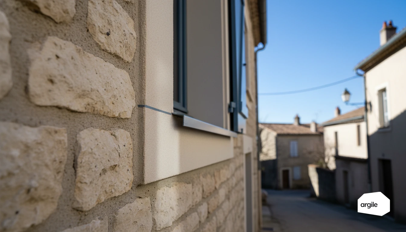
When a thermal break connector isn't possible, the goal is to "break the path" of thermal bridges. External wall insulation (ITE) remains the most effective because it wraps around the slab-wall junction. With internal wall insulation (ITI), plan an insulation return at reveals, slab edges and load-bearing partitions, and treat the joinery with suitable liners. A continuous lining, well connected to the ceiling and floors, avoids cold zones. On an external insulation job, Argile measures the facade areas and picks the system from up-to-date catalogues.
Sensitive cases: timber floors, old walls, stone, co-owned buildings and footprint constraints
With timber floors and old walls, watch out for moisture. Insulation that's too airtight can shift the dew point. On stone, favour vapour-permeable solutions and careful detailing. In co-owned buildings, ITE can be limited by the facades, alignment rules and footprint. In that case, aim for targeted treatments, as close as possible to the junctions, and document the choices to secure performance.
Costing, client arguments and 2026 requirements: selling the right solution
How to cost without eating into your margin: supply, labour, contingencies and interfaces between trades
Cost item by item: removal, thermal bridge treatment, insulation, airtightness, finishes. Separate supply and labour, then add an "interfaces" line item (plastering, electrical, mechanical ventilation, joinery) to avoid gaps between trades. That line is detailed in the quote with a works library and free-text lines. Plan for site contingencies (access, moisture, surprises behind wall linings) and clearly define what triggers a change order.
- Measurements and photos at the site survey.
- Written assumptions (surfaces, thicknesses, substrates).
- Schedule by trade to limit rework.
A simple pitch for the client: comfort, moisture, bills and durability of the work
With the client, stay concrete. Explain that you're treating comfort and moisture first. Fewer cold surfaces means less condensation and healthier air. With a more continuous envelope, the bill goes down, and the work lasts. Highlight winter and summer comfort, not incomprehensible figures.
Points to frame in 2026: consistency with the energy audit, performance requirements and aid file (depending on the works)
In 2026, align your proposal with the energy audit when it's required or already done. Check the performance criteria (thermal resistances, COP/ETAS depending on the equipment) and RGE requirements. On financial aid, insulation no longer opens a per-measure MaPrimeRénov' grant since 1 September 2026 (decree no. 2026-822, walls having left as early as 1 January 2026 under decree no. 2025-956): it is funded through CEE or within the supported route. For these applications, plan ahead for the complete file: detailed quote, CEE data sheet references, certificates, work start dates, and proof of compliance. To limit callbacks and secure payments, apply a clear method to avoid MaPrimeRénov' file rejections.