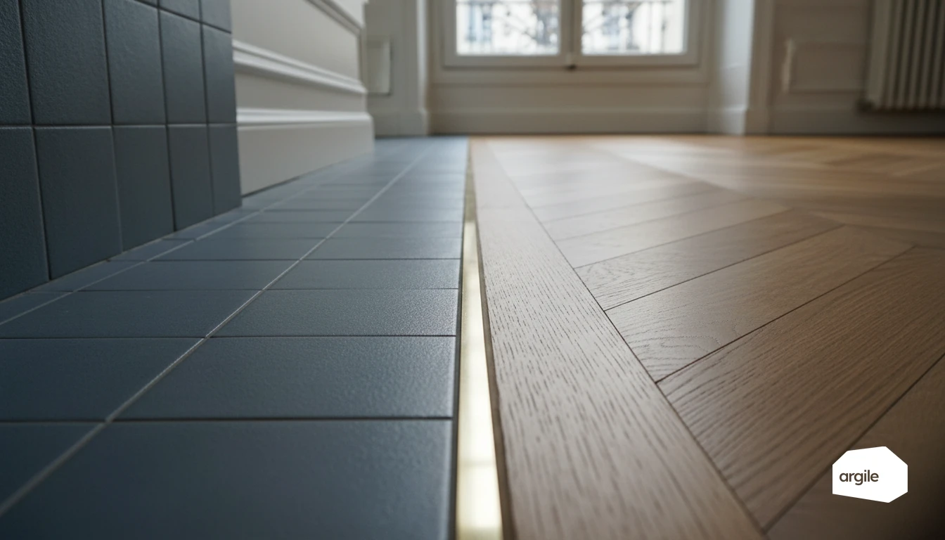
With internal wall insulation, the intermediate floor passes through the wall and cuts the insulation: the linear coefficient of the junction sits between 0.5 and 1.0 W/(m·K) untreated, and comes back down to between 0.2 and 0.4 W/(m·K) with an insulation return. On a timber floor, the thermal bridge plays out on the joist ends and their bearings in the wall, and on a beam-and-block or concrete floor on the slab edge and the cross-walls connecting to the facade. The insulation return extends 60 to 100 cm on the underside where the space below is accessible, or is handled as a high and low skirting with the vapour check carried through and sealed. Internal wall insulation also costs 5 to 10% of living area, a figure to state to the client before signature rather than when the rails go up.
Understanding the thermal bridge at the intermediate floor in ITI
Why the intermediate floor creates a break in insulation in ITI
In ITI, the insulation lines the inner face of the wall. The trouble is that the intermediate floor, often concrete, passes through the wall and rests inside it. As a result, the insulation stops at the slab. Heat then finds a "shortcut" through the structure. It's a hard point, difficult to fix retroactively if you don't anticipate it.
Spotting risk zones: wall/floor junctions, partition walls, slab edges
On site, watch the junction between the external wall and the floor, but also the partition walls that connect to the façade. The slab edge and the floor ends on the exterior side are classic zones. Shutter boxes and recesses near the floor can amplify the phenomenon.
Measuring the impact: comfort, condensation, consumption (what you see on site)
Clients often describe a "cold floor" or a cooler band at the base of the wall. You sometimes see black marks in corners, a sign of condensation and mould when indoor air is humid. On the energy side, the heating runs longer to compensate for this leak, especially on exposed façades: it's typical of the weak points of the building envelope.
Diagnosing before work starts: what to check on site
Identifying the floor type: timber, beam-and-block, concrete, and consequences for ITI
Before an ITI, look at the floor at the base of the walls. With a timber floor, check the condition of the joists, the bearings and the service routes. The frame fixings and the treatment of the wall-floor junction must limit thermal bridges. With beam-and-block or concrete floors, identify the slab edges and partition walls. These are often the zones that need care, with an insulation return and clean airtightness treatment.
Checking moisture and ventilation: avoiding condensation after ITI
Measure, or at least assess, the moisture level. Stains, efflorescence, odours, cold wall base, infiltration through the façade or the ground. Without effective ventilation, the insulation can trap vapour and create mould and delamination. Check the mechanical ventilation, the air inlets, the extraction in wet rooms, and plan a vapour-barrier or vapour-check continuity suited to the build-up.
Relying on the energy audit and what's expected in 2026 (documents, photos, traceability)
The audit and supporting documents become your guiding thread. In 2026, you'll increasingly be asked for clear traceability. Keep the audit, the plans, the technical data sheets (insulation, membranes), the RGE certificates, and dated photos before, during and after. This is useful for MaPrimeRénov' and CEE, and above all to prove that the ITI was installed without a break in continuity.
ITI solutions for treating the intermediate-floor thermal bridge
Continuity of the insulation: returns on the underside and as a high skirting (depending on access)
In ITI, the thermal bridge often appears at the floor, which cuts the wall insulation. The reflex is continuity. If you have access to the space below, extend the insulation on the underside by 60 to 100 cm. Otherwise, plan for an insulating high skirting board on the room side, connected to the wall insulation, to "wrap" the junction.
Treating the slab edge: thermal breaks, localised insulation, insulating boxing in renovation
The slab edge remains a cold zone. In renovation, localised insulation is often the target. A thin insulating box on the interior side, insulated cladding at the floor, or a supplement on the façade side where possible. Thermal breaks are more reserved for major floor rework. The goal is to reduce the area of concrete exposed to the heated volume.
Airtightness and vapour barrier: wall/floor junctions to limit leaks
High-performance insulation is also about air. Take care over the wall/floor junctions with adhesive tapes, sealant and membrane returns. The vapour barrier or vapour-check membrane must remain continuous, especially if the insulation is moisture-sensitive. Fewer leaks means more comfort and less risk of condensation inside the wall.
Implementation: the details that make the difference (and prevent rework)
Critical points not to miss: cable runs, boxes, hatches and ducts
In ITI, air and vapour leaks often happen through the "small holes". Treat every penetration as a sensitive zone. Fit sleeves or sealing tape around ducts. Plan for sealed electrical boxes, an insulated and sealed hatch, and cable routing thought through before closing up.
Material compatibility: mineral wool, wood fibre, EPS, boards and renders
Don't mix materials at random. Wood fibre and mineral wool don't manage moisture the same way as EPS. Check for a vapour barrier or a vapour-variable membrane depending on the build-up. Choose boards and renders compatible with the substrate. Follow the technical approvals of the systems used.
Quality checks: tests, readings and simple self-checks to plan on site
Before closing up, do a "photo" walk-through. Check joint continuity, installed thickness, bearings and thermal bridges at junctions. If possible, plan an airtightness test or a smoke test. A moisture reading of the substrates avoids nasty surprises. Keep a simple checklist.
Budget, grants and RGE requirements: securing your paperwork in 2026
Cost items in ITI: labour, finishes, thermal-bridge treatment at the floor
In ITI, the budget mainly comes down to labour (removal, framing, fitting the insulation, airtightness), then finishes (boards, tape, paint, electrical rework), which price up as second-fix works in their own right rather than as a lump sum. Keep a dedicated budget line for the base of the wall. That's where the floor thermal bridge is treated, with insulation continuity and properly connected membranes. Plasterer software prices those lines from the survey measurements, and the boards, tracks and studs follow from the same areas.
Grants available in 2026: MaPrimeRénov' and CEE (documents to provide as the tradesperson)
Since 1 January 2026, ITI sold on its own no longer opens a single-measure MaPrimeRénov' grant: it is funded by the CEE grant under standard sheet BAR-EN-102, the 5.5% VAT rate and the éco-PTZ, and MaPrimeRénov' only comes back through the Parcours accompagné, in a whole-house renovation. The documents stay the same:
- Quote signed before work starts, with surface areas, target thermal resistance and product references.
- Itemised invoice, dates, job-site address, RGE mentions, performance figures, quantities installed.
- Up-to-date RGE certificate and, for CEE, a co-signed sworn statement.
RGE best practices: proof of installation and common mistakes that block grants
Keep photographic evidence (before, critical points, after) and the technical data sheets. Blockages often come from a quote dated after work started, an RGE qualification that doesn't match the trade category, or an R-value that doesn't match the product actually installed. A clear file is like good insulation: it avoids leaks.