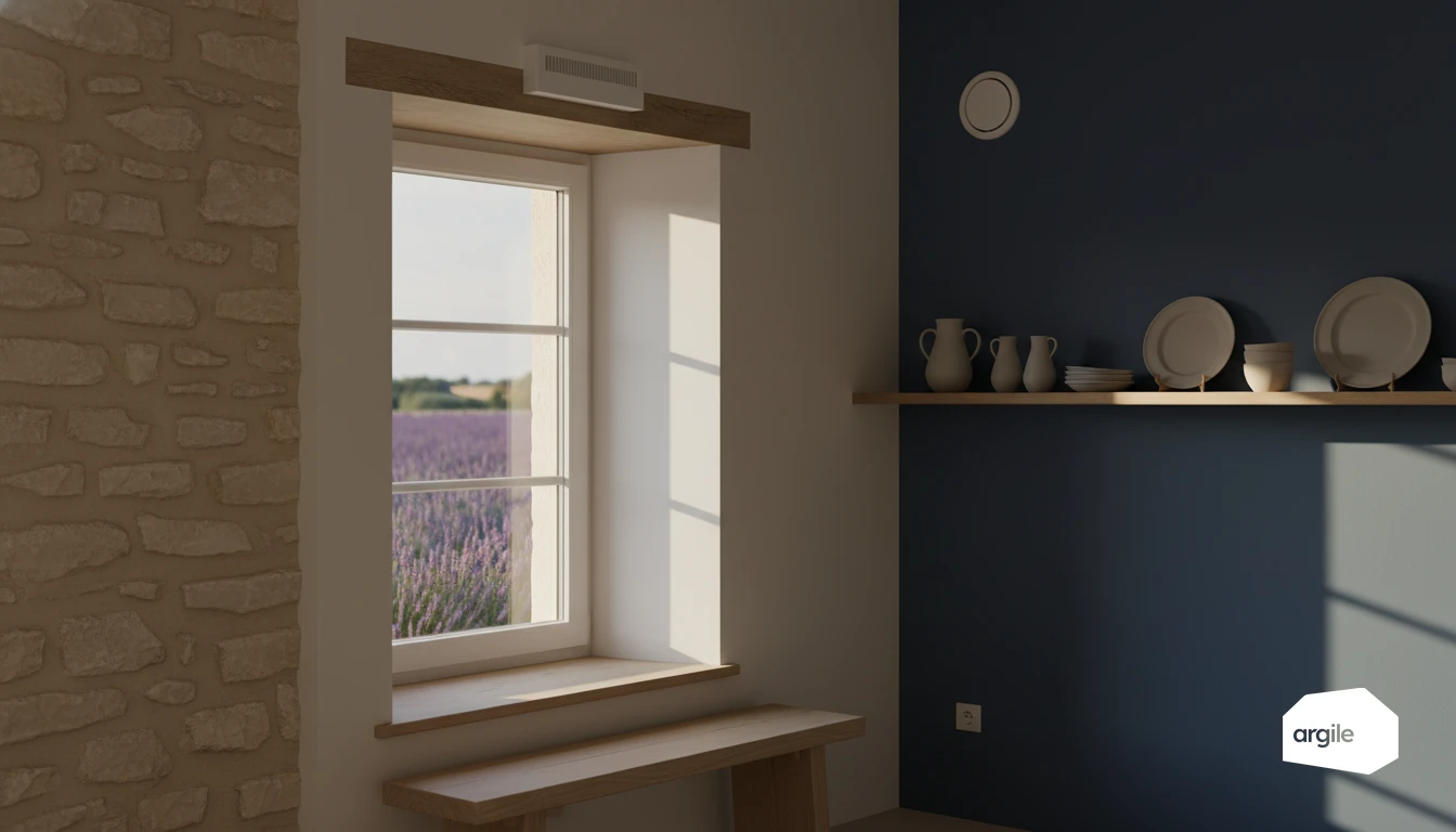
To know where to place an extract vent, three rules are enough: in the service rooms (kitchen, bathroom, WC), high up, and opposite the door the air comes in by, so the flow sweeps the room before being extracted. The French NF DTU 68.3 sets the vent at least 1.80 m above the floor and its axis at least 20 cm from the adjacent surfaces. A utility room, for its part, does not appear in the list of service rooms in the French order of 24 March 1982. It therefore carries no regulatory extract rate, unlike the wet rooms whose rate is read line by line from the regulatory tables, which does not mean leaving it alone: it is the biggest moisture producer in the dwelling after the bathroom.
Understanding the role of air inlets and extract vents in ventilation
Balancing fresh and extracted air: the principle behind a working MVHR system
Effective ventilation is a circuit. Fresh air comes in through the air inlets, stale air goes out through the extract vents. If either is missing, the MVHR system strains, makes noise, and pulls air from wherever it can. The goal is a continuous air path between rooms, with undercuts beneath doors.
Knowing where to place air inlets (on windows) and vents (in wet rooms)
Air inlets go on the windows of living rooms, such as the lounge and bedrooms. Vents go in the wet rooms, kitchen, bathroom, WC, utility room, generally high on the wall. On site, also check that nothing blocks the grilles, paint, cladding, furniture.
Spotting the signs of poor ventilation on site (condensation, odours, mould)
Warning signs come quickly. Frequent condensation on glazing, odours that linger after a shower or cooking, mould in corners or behind furniture. At this point, check airflow rates, duct condition, and whether the air inlets are actually open. These are your early warning signs before real damage sets in. To go further on technical points that often get overlooked, see also duct condition.
Where to place an extract vent, room by room
The vent goes where moisture and odours are produced, as high as possible, and away from where the air comes in. What follows applies to a single-flow extract system as much as to the extract network of an MVHR unit. It is also what the survey records room by room: kitchen, bathroom and WC photographed, placed on the plan, each with the vent it receives.
Which room gets what: air inlet or extract vent
The principle is simple and often reversed on site: fresh air enters through the main rooms, it is extracted in the service rooms, and it moves freely between the two. France's Agence Qualité Construction records as a common defect the presence of air inlets in service rooms, which short circuits the whole sweep.
| Room | Air inlet | Extract valve | Regulatory rate |
|---|---|---|---|
| Living room, bedroom, study | yes | no | not applicable, these are the main rooms |
| Kitchen | no | yes | 20 to 45 m³/h continuous, 75 to 135 m³/h boost |
| Bathroom or shower room | no | yes | 15 or 30 m³/h by dwelling size |
| WC | no | yes | 15 or 30 m³/h by dwelling size |
| Utility room, store, dressing room | no | advisable, not required | no rate set by the order |
| Bedroom with cooking facilities | yes | yes | both a main and a service room, article 6 |
Extract vent clearance from the ceiling and walls
Two dimensions come from the NF DTU 68.3 and are checked with a tape measure: the height, at least 1.80 m above the finished floor, and the clearance, at least 20 cm between the axis of the vent and the adjacent surfaces. The ceiling clearance of a wall-mounted vent follows from the same rule, and manufacturers' instructions spell it out. France's Agence Qualité Construction regularly sees these two dimensions missed.
| Installation dimension | Usual value | Where it comes from |
|---|---|---|
| Height of a wall-mounted vent | 1.80 m minimum above the floor | NF DTU 68.3 |
| Vent axis to the nearest wall or corner | 20 cm minimum | NF DTU 68.3 |
| Axis of a wall-mounted vent below the ceiling | about 20 cm, top edge around ten centimetres down | manufacturers' instructions, usual recommendation |
| Axis of a ceiling vent to the nearest wall | 20 cm minimum | NF DTU 68.3, to cross-check with the instructions |
| Vent and the door the air comes in by | as far apart as possible, opposite sides | sweep principle, not a dimension |
A vent tucked into a corner or behind a unit added later will not deliver its rate, whatever the fan. The clearance also serves the inspection: without room around the vent, the measuring cone cannot be fitted and the handover airflow cannot be read.
Where to place the extract vent in a bathroom
High up, on the shower or bath side, opposite the door. Air comes in under the door, crosses the room and leaves at the vent. Fitted just above the door, the vent draws the air that has only just arrived and leaves the steam hanging over the shower. Ceiling or top of wall both work as long as the dimensions in the table hold.
Then there is the wiring. A self-regulating vent, or a battery-powered humidity-controlled one, has no cable and can go anywhere. A powered vent (timer on the light switch, presence detection) falls under the zones of the French NF C 15-100: never in zone 0 or zone 1, directly above the shower or bath, and in zone 2 only if its class and protection rating allow it. That is why manufacturers offer these vents in 12 V extra-low voltage or with a battery. Note the zones on site before choosing the model, not after the cable has been pulled.
Where to place the extract vent in the kitchen
High up, near the cooking area, where steam and grease are produced, but not in the plume directly above the hob, where it clogs within weeks. In practice: high on the wall or on the ceiling, beside the hood rather than above it, and away from the door. The kitchen vent often carries two rates (base and boost, operated by pull cord, switch or timer): it must stay reachable, which rules out the back of a wall cabinet.
No single distance separates the vent from the hood. The idea is that neither short-circuits the other. One rule, however, is not up for debate: a powered cooker hood is never connected to the ventilation network or fan unit. It would unbalance every airflow, send grease into the ducts and could push air back into other rooms. A recirculating hood, or an extracting hood on its own duct with a make-up air supply: the compatible set-ups are detailed in cooker hood and ventilation. With a flued gas boiler in the kitchen, you move to gas-safe mechanical ventilation, with a dedicated vent and safety device, which is another job.
WC: high up, above the toilet
Vent high up, above or beside the toilet, opposite the door. In a narrow WC, the 20 cm clearance from the side wall often decides between the back wall and the ceiling. Presence-detection vents are common there, and how models that modulate on humidity work is explained in humidity-controlled vent.
Ventilation in a utility room or store room: does it need a vent?
Since the order does not require it, the utility room is a documented decision. A vented tumble dryer, a washing machine and drying laundry put several litres of water a day into a room that is often closed and rarely heated: exactly the conditions for condensation. Three options depending on the layout, all to be written into the quotation.
| Option | What it assumes |
|---|---|
| Extract the utility room on the existing network | Checking the unit takes the extra flow without starving the other valves |
| A timed extract of its own | A closed room |
| Relying on the neighbouring service room that is already served | A utility room that opens onto it, and air transfer that actually happens, so an undercut door or a grille and not a solid door fitted by the joiner after you left |
In all three cases the sentence on the quotation is the same: what is treated, what is not, and why. That is what protects you the day mould appears behind the machine.
A store room follows the same logic. If it sits inside the heated envelope and houses a washing machine or a freezer, treat it like a utility room. If it is outside the heated envelope and closed off from the dwelling, it is not connected to the network: the vent would draw the dwelling's warm air to ventilate a cold space, with condensation in the duct as a bonus.
Door undercuts: the air path the vent relies on
A well-placed vent is useless if the air cannot reach it. The sweep passes under the interior doors. Common practice is to undercut the doors of main rooms and bathrooms by about 1 cm, and the kitchen door, which carries the largest rate, by about 2 cm, or to fit a transfer grille of equivalent free area. These are site rules of thumb: free areas are checked against the NF DTU 68.3 and the system instructions.
The trap comes after you: a door replaced or a thick floor covering laid after handover, which closes the gap. Record the undercut in the handover report and tell the client. Bedrooms, for their part, receive fresh air and no vent; their case (noise, air inlet, night-time comfort) is covered in ventilation and sleep quality.
Sizing: how to calculate MVHR airflow rates without getting it wrong
Determining regulatory airflow rates based on the dwelling and its rooms
Start with the minimums from the decree of 24 March 1982. They depend on the type of dwelling and the number of main rooms. You add up the extract rates of the service rooms. In practice, the kitchen often carries the peak rate. A solid baseline avoids ventilation that is either too weak or needlessly noisy.
Accounting for pressure drop: ductwork, lengths, elbows and fittings
Next, translate the plan into metres of ducting and equivalent lengths for every elbow, tee, vent, damper, silencer and filter. The sum gives the pressure to overcome (Pa). Aim for a short network with few changes of direction. Keep a simple margin for fouling.
Choosing the right MVHR unit: single-flow, humidity-controlled, heat-recovery
Select the unit based on its performance curve. It must deliver the total airflow at the calculated pressure level. In single-flow, the humidity-controlled version modulates but must still respect the minimums. In heat-recovery systems, also size the supply air and allow for losses through the heat exchanger and filters to keep ventilation stable (see also single-flow, the humidity-controlled option).
Air inlets: choosing and installing them correctly to avoid client complaints
Selecting the right type of air inlet: self-regulating, humidity-controlled, acoustic
An air inlet feeds the ventilation system with fresh air. Choose it based on the system. The self-regulating type keeps a near-constant flow rate. The humidity-controlled type modulates according to humidity, useful in a dwelling with variable occupancy. The acoustic type adds attenuation where the dwelling faces a noisy street.
Limiting noise, draughts and fouling: good installation practice
Follow the manufacturer's instructions and check MVHR compatibility. Install it high on the window, with a continuous seal and fixings that don't twist the frame. Take care with airtightness on the interior side, and keep the exterior passage clear. Avoid paint and site dust getting into the damper. Warn the client. Regular dusting limits whistling and blockages.
Handling special cases: external/internal wall insulation, new windows, sensitive rooms
With external or internal wall insulation, use a suitable sleeve and maintain insulation continuity to avoid thermal bridges. With new windows, plan for the recesses and compatible accessories ahead of time. In bedrooms or sensitive rooms, favour acoustic models and avoid blowing air directly onto a bed or sofa.
Extract vents: settings and airflow checks
Making the adjustments: calibration, balancing, maintenance markers
Set each vent to its target airflow (calibration), then check that the whole network stays consistent (balancing). Work within the manufacturer's settings, without improvising. Note the setting positions and add a simple marker (label, photo, date) to make maintenance easier and prevent drift after cleaning.
Checking on site: airflow measurements, smoke tests, simple traceable checks
Check on site with a flow-measuring cone or a suitable anemometer. Complement this with a smoke pencil or paper test to confirm flow direction and spot a fouled vent or an airtightness defect. Keep a record. A dated and signed table of per-room measurements secures the handover and future inspections. To go further, see airflow measurements and the right tools for the job.
In 2026, secure your ventilation jobs with a clear handover method
Documenting sizing and installation: plans, photos, product datasheets
For ventilation that stands up to time and inspections, keep a record of the sizing. Airflow calculation notes, a layout plan of the ductwork, and the location of vents and air inlets. Add the product datasheets (unit, vents, ducts, fittings) and the setting instructions. A few dated photos make a difference, taken before cladding is closed up and in the loft, all the more so when they are captured during the survey and attached to the property file along with the position of each unit on the plan.
Coordinating ventilation with airtightness and insulation: avoiding classic mistakes
Ventilation cannot be handled in isolation. Plan ahead for penetrations through membranes and vapour barriers. Take care with sleeves and adhesive tapes, or you create leaks and unwanted return airflow. Also think about insulating ducts in unheated spaces. Skip that, and you're inviting condensation and losses. Aim for clean, accessible junctions.
Setting up a handover checklist and a maintenance guide for the client
At handover, validate everything in writing.
What to validate at handover
- Airflow rates measured at the vents.
- Settings.
- Noise.
- Direction of operation.
- Filter access.
- Condensate drainage if applicable.
Hand over a signed checklist, the installation diagram, and a simple maintenance guide. For example, cleaning the vents and replacing filters according to the manual. The client breathes easier, and so do you.