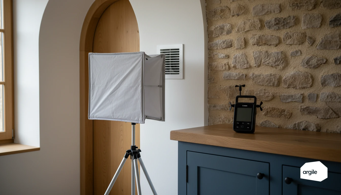
Pour contrôler un débit d'air, l'appareil se choisit d'après le point de mesure : cône ou balomètre sur une bouche, tube de Pitot relié à un manomètre différentiel ou anémomètre à fil chaud dans une gaine, par un trou de mesure percé en section droite. Dans une gaine, le débit vaut la vitesse moyenne multipliée par la section, si bien que 1 m/s dans un conduit de 125 mm fait 44 m³/h. Le chiffre relevé ne vaut que comparé à l'exigence de l'arrêté du 24 mars 1982, entre 15 et 45 m³/h par bouche en permanent selon la pièce et jusqu'à 135 m³/h en pointe cuisine. Avant de conclure qu'un caisson est en cause, vérifiez la pose : une bouche à moins de 1,80 m du sol ou à moins de 20 cm de ses parois adjacentes ne délivrera jamais sa valeur nominale.
Pourquoi mesurer le débit de ventilation sur chantier en 2026
Assurer la qualité d’air et éviter les moisissures : les points à contrôler
Une ventilation qui débite comme prévu, c’est votre meilleur allié contre l’humidité. Sur chantier, vérifiez le débit réel aux bouches, l’état des réseaux et la continuité des entrées d’air.
- Débits pièce par pièce, selon le type de logement et le système.
- Absence d’obstruction, gaines bien raccordées, fuites limitées.
- Fonctionnement des vitesses et bon positionnement des bouches.
Repérer une ventilation sous-dimensionnée ou mal réglée : ce que vous relevez
Condensation sur les vitrages, moisissures en angle de pièce humide ou bouche qui ne retient pas une feuille de papier orientent le diagnostic, ils ne le concluent pas. Ce qui le conclut, c’est le relevé : débit par bouche comparé à la typologie, longueur et tracé du réseau, état du caisson et de ses vitesses, présence et calibrage des entrées d’air. Un réseau trop long, un ventilateur fatigué ou un mauvais équilibrage se distinguent à ce relevé, pas à l’œil.
Sécuriser vos chantiers : traçabilité du diagnostic et attentes des clients
Une mesure non tracée ne protège personne en cas de réclamation. Conservez une fiche de mesures (date, appareil, valeurs, réglages). C’est votre preuve à la réception et un support simple pour expliquer l’entretien de la ventilation.
Ce qu'on mesure, et à quoi on le compare
L'erreur la plus fréquente n'est pas dans l'instrument, elle est dans la référence. Un débit relevé sans typologie du logement ne veut rien dire, puisque l'exigence dépend du nombre de pièces principales. C'est aussi pour cela qu'un taux de renouvellement d'air en vol/h ne se contrôle pas directement : il se déduit du débit total mesuré, divisé par le volume.
| Point de mesure | Valeur de comparaison | D'où elle vient |
|---|---|---|
| Bouche cuisine, régime permanent | 20 à 45 m³/h selon la typologie | article 4 |
| Bouche cuisine, régime de pointe | 75 à 135 m³/h selon la typologie | article 3 |
| Bouche salle de bains | 15 ou 30 m³/h selon la typologie | article 3 |
| Bouche WC | 15 ou 30 m³/h selon la typologie | article 3 |
| Somme des bouches, régime permanent | 35 à 135 m³/h selon la typologie | article 4 |
Notez la dernière ligne : c'est la seule qui se contrôle sans ambiguïté, parce qu'elle ne dépend pas de la répartition entre bouches. Si la somme y est mais qu'une bouche est faible, le problème est un équilibrage. Si la somme n'y est pas, cherchez le réseau ou le caisson.
L'ordre des vérifications, avant d'accuser le caisson
Commencez par ce qui ne coûte rien. La bouche est-elle à sa hauteur et à ses distances, ou bien un meuble a-t-il été poussé devant depuis la réception ? Les entrées d'air des pièces principales sont-elles présentes, calibrées, non obturées et surtout absentes des pièces de service ? Le transit d'air passe-t-il réellement, détalonnage de porte ou grille, ou bien un bloc-porte plein a-t-il été posé après coup ?
Ces trois points couvrent l'essentiel des non-qualités relevées par l'Agence Qualité Construction sur les installations simple flux, et ils s'observent sans instrument. Ce n'est qu'ensuite que la mesure devient informative, parce qu'elle porte alors sur un réseau dont la géométrie est correcte.
Deux conseils de traçabilité pour finir. Consignez la typologie du logement en tête du relevé, sans quoi vos valeurs ne seront pas relisibles dans six mois. Et mesurez en pointe comme en permanent : c'est en pointe que les écarts se voient, et c'est en pointe que le client se plaindra.
Ce que vous mesurez vraiment : débit, pression et équilibrage de la ventilation
Débit d’air extrait et soufflé : ordres de grandeur et erreurs fréquentes
Le débit, c’est la quantité d’air réellement déplacée. En logement, on parle souvent de quelques dizaines de m³/h par bouche, avec des pointes plus hautes en cuisine. L’erreur classique est de mesurer trop vite. Sans cône de mesure, avec une grille encrassée ou une porte fermée, votre lecture débit peut être faussée.
Pression disponible, pertes de charge et impact des réseaux (bouches, gaines, coudes)
Une ventilation peut être “bonne sur le papier” et insuffisante sur site si la pression disponible est mangée par les pertes de charge. Gaines trop longues, coudes serrés, réduction de diamètre, bouches trop restrictives. Résultat, le débit chute, le bruit monte. Visez un réseau le plus simple possible, étanche et bien dimensionné, en particulier sur l’isolation des gaines de ventilation en combles non chauffés.
Équilibrage pièce par pièce : cuisine, bains, WC, chambres et pièces de vie
L’équilibrage, c’est répartir. On extrait plus en cuisine, bains et WC. On apporte l’air neuf via entrées d’air ou soufflage vers les pièces de vie et chambres, puis on laisse circuler sous les portes. Réglez, puis re-mesurez. Un bon équilibrage pièce évite humidité, odeurs et inconfort. En collectif, le même travail se reprend niveau par niveau, parce que la dépression varie du pied à la tête d’une colonne d’extraction commune.
Outils de diagnostic pour la mesure du débit de ventilation
Quel contrôleur de débit pour quel point de mesure
Il n’existe pas de contrôleur de débit universel : chaque point du réseau a son instrument, et un appareil utilisé hors de son point de mesure donne un chiffre faux avec assurance.
| Point de mesure | Contrôleur à utiliser | Ce qu’il donne | Piège principal |
|---|---|---|---|
| Bouche d’extraction ou de soufflage | cône de mesure avec anémomètre à hélice, ou balomètre | débit en m³/h, lecture directe | fuite entre le cône et le support, régime non stabilisé |
| Gaine rigide | tube de Pitot et manomètre différentiel, ou anémomètre à fil chaud | vitesse en m/s, à multiplier par la section | mesure au seul centre de la gaine, trop près d’un coude |
| Bouche autoréglable ou hygroréglable | manomètre différentiel sur la prise de pression | dépression à la bouche, en Pa | conclure sans la plage de fonctionnement de l’avis technique |
| Caisson | manomètre différentiel aux prises du caisson | pression disponible, à lire sur la courbe du fabricant | confondre pression du caisson et débit délivré aux bouches |
Sur une installation de logement, la mesure en bouche suffit dans la grande majorité des cas, parce que c’est à la bouche que l’arrêté fixe l’exigence. La mesure en gaine sert à localiser une perte : un débit correct au départ du caisson et faible en bout de réseau désigne une fuite ou un écrasement entre les deux, ce que traite l’étanchéité des gaines de VMC.
Mesurer dans une gaine : trou de mesure, section droite et débit par diamètre
Percez le trou de mesure dans une portion rigide et rectiligne, loin des coudes, des réductions et des piquages, là où l’écoulement est établi. Relevez la vitesse en plusieurs points sur le diamètre et faites la moyenne, puis multipliez par la section intérieure. Rebouchez le trou avec un obturateur ou un adhésif adapté. Le tableau donne le débit correspondant à une vitesse moyenne lue, pour les diamètres courants en logement.
| Diamètre de gaine | Section | Débit à 1 m/s | Débit à 2 m/s | Débit à 3 m/s |
|---|---|---|---|---|
| 80 mm | 0,0050 m² | 18 m³/h | 36 m³/h | 54 m³/h |
| 125 mm | 0,0123 m² | 44 m³/h | 88 m³/h | 133 m³/h |
| 160 mm | 0,0201 m² | 72 m³/h | 145 m³/h | 217 m³/h |
| 200 mm | 0,0314 m² | 113 m³/h | 226 m³/h | 339 m³/h |
Lu dans l’autre sens, le tableau sert aussi au dimensionnement : une pointe cuisine de 135 m³/h dans un conduit de 125 mm impose 3 m/s, une vitesse élevée pour un réseau de logement où le bruit se surveille, d’où l’intérêt du 160 mm sur le tronçon cuisine des grandes typologies.
Anémomètre et cône de mesure : choisir le bon matériel selon les bouches
Pour un diagnostic de ventilation fiable, l’anémomètre seul suffit rarement sur une bouche. Il est plus juste avec un cône de mesure, surtout sur des bouches circulaires ou des entrées d’air où le flux est turbulent. Vérifiez l’étanchéité du cône sur le support, stabilisez le régime quelques secondes, puis relevez plusieurs points si la bouche est large.
Balomètre (hotte de mesure) : quand il fait gagner du temps et quand il piège
Le balomètre est un vrai gain de temps sur chantier quand les bouches sont accessibles et répétitives. Il peut piéger si la hotte fuit, si la grille est trop proche d’un obstacle, ou si la vitesse est faible, avec des erreurs par recirculation dans la hotte. Un contrôle croisé sur une bouche avec cône aide à caler l’écart.
Mesure indirecte : manomètre, fumigènes et tests simples pour compléter le diagnostic
Complétez la mesure de débit par un manomètre pour lire la pression utile (encrassement, réseau écrasé, déséquilibre). Les fumigènes, ou un simple papier fin, valident le sens d’air et les entrées parasites. Ces tests ne remplacent pas un débit mesuré, mais ils expliquent vite pourquoi la ventilation ne tient pas ses valeurs.
Méthode terrain : réussir vos mesures de débit sans fausser le diagnostic
Préparer l’intervention : état des bouches, filtres, portes, fenêtres et régime de la VMC
Avant toute mesure, remettez l’installation dans une configuration stable. Bouches accessibles et propres, filtres dépoussiérés, pas de cache ni de grille déformée. Fermez les fenêtres. Placez les portes intérieures dans la position d’usage et notez-la. Mettez la VMC en régime normal, sans mode boost. Attendez quelques minutes pour que la ventilation se stabilise.
Réaliser les relevés : positionnement de l’outil, temps de stabilisation et répétitions utiles
Utilisez un cône ou une cloche de mesure adaptée, bien centrée sur la bouche, sans fuite sur les côtés. Gardez l’outil immobile. Laissez la lecture se stabiliser, puis relevez. Faites 3 passages et conservez la moyenne. Un résultat isolé est souvent un faux bon chiffre.
Consigner et interpréter : tableau de mesures, écarts, actions correctives (réglages, nettoyage, remplacement)
Consignez pièce par pièce. Débit mesuré, réglage de bouche, observations. Si l’écart est vraiment marqué, commencez simple. Nettoyage des bouches et filtres, vérification des gaines écrasées, puis réglage. Si le ventilateur ou une bouche est usé, remplacez. Re-mesurez après chaque action. Argile rattache ces relevés et les photos au dossier du chantier, pièce par pièce.
Cas pratiques et bonnes décisions après diagnostic de ventilation
VMC simple flux : réglage des bouches, détection des fuites et priorités de remise en état
Après mesures de débits, commencez par le basique. Nettoyage des bouches, contrôle des clapets et des entrées d’air. Repérez les gaines écrasées, déboîtées ou percées en combles. Une fuite peut “pomper” l’air au mauvais endroit. Réparez et étanchéifiez en priorité, puis ajustez les bouches.
VMC double flux : contrôle des débits, des filtres et des déséquilibres de réseau
Vérifiez l’état des filtres et l’échangeur. Un filtre propre évite la perte de débit et protège la machine. Mesurez soufflage et extraction pièce par pièce. Si ça dérive, cherchez un registre fermé, une gaine pincée, un réseau mal isolé ou un mauvais équilibrage. Corrigez avant de toucher aux vitesses.
Après isolation ou changement de menuiseries : vérifier le débit de ventilation et adapter les entrées d’air
Plus vous rendez un bâti étanche, plus la ventilation devient le poste qui vous reviendra dessus. Confirmez les débits réglementaires au relevé, vérifiez que les détalonnages de portes survivent au second œuvre, et remplacez les grilles inadaptées avant la réception plutôt qu'en SAV. L'objectif à tenir est un débit suffisant sans courants d'air, avec des entrées d'air dimensionnées et non sécables laissées en place. Ces détalonnages et ces entrées d'air se notent au relevé plutôt qu'en SAV : la visite les pointe pièce par pièce, avec le caisson et le matériel du geste.