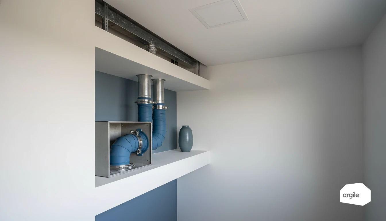
NF DTU 68.3 imposes no airtightness class on dwelling ventilation ductwork, contrary to what is often written. What it imposes is a leakage allowance to be built into the sizing: 12% of the diversified flow rate at each vent, cut to 5% where the whole network is assembled with fittings carrying class C seals as a minimum. On an existing network reused in a retrofit, the default allowance rises to 30% of the reduced nominal flow, and above 30% measured, reuse is ruled out. The A, B, C and D classes of EN 12237 remain the unit in which a requirement is written into a quote, each one three times tighter than the one before.
Understanding air losses on a ventilation system and their impact on the job
Where air is lost most often: connections, penetrations, take-offs and units
Leaks concentrate at the joints, not along the straight runs. Sleeves not pushed fully home, lipped seals aged or missing, push-in take-offs fitted without additional sealing, untreated wall penetrations, cable glands and unit covers poorly jointed. On flexible ductwork, crushing where it passes through the framing adds a permanent loss of cross-section that compounds the leakage, and never shows once the ceilings are closed up.
What a leak actually produces, and why it depends on the unit
This is where the diagnosis is won, and the mechanism is not the one people assume. Two cases are mutually exclusive. If the unit does not compensate for the leaks, the flow no longer reaches the vents and the dwelling is under-ventilated: that is the visible case, the one that produces moisture and odour back-draught. If the unit regulates at constant pressure and compensates, the flow rates at the vents stay correct, air quality is not degraded, and the leak is only paid for in fan consumption. A leaky network therefore has no single signature, which is why it gets missed when only the vents are checked.
Spotting the signs on site: joints, condensation, dust and measurement gaps
On site, look for dust trails around the fittings, which mark a permanent air path, whistling at joints under negative pressure, and condensation in the loft around the penetrations. Confirmation is instrumental: a flow reading at each vent, a pressure reading at the unit, and comparison against the sizing. A compliant flow rate with an abnormally high pressure at the unit is the signature of a leaking network with a fan compensating for it.
Choosing the right ducts and fittings for lasting airtightness
Flexible or rigid ducts: advantages, limits and uses by run
Rigid duct, PVC or metal, is the only one that keeps its cross-section and can be made airtight repeatably over a length. It limits pressure drop and takes range-matched sealed fittings. Flexible is for a short connection to work around an obstacle or to decouple, never for a main run. In a loft it is suspended at regular spacing to avoid sagging, and it does not cross framing without a sleeve.
Fittings, sleeves, clips, seals: aiming for compatibility and long-term performance
Airtightness is decided at the joints, and it is lost as soon as ranges are mixed. Choose parts from the same range and the same diameter, with suitable seals.
- A sleeve with a seal or a lip, never a dry push-fit.
- A correctly sized screw clip, tightened without deforming the section.
- A sealant or ducting tape compatible with the duct material.
Airtightness classes and leakage allowances: what the text actually requires
The classes come from EN 12237 for circular ducts and EN 1507 for rectangular ones. They set not a percentage but a maximum leakage rate referred to the internal developed surface of the network, at a test pressure: f = k × p^0.65, in litres per second per square metre, with p in pascals.
| Class | Constant k | Allowable leakage at 250 Pa | Allowable leakage at 400 Pa |
|---|---|---|---|
| A | 0.027 | 0.98 L/(s·m²) | 1.33 L/(s·m²) |
| B | 0.009 | 0.33 L/(s·m²) | 0.44 L/(s·m²) |
| C | 0.003 | 0.11 L/(s·m²) | 0.15 L/(s·m²) |
| D | 0.001 | 0.04 L/(s·m²) | 0.05 L/(s·m²) |
From one class to the next, the allowable leakage rate is divided by exactly three. Class D is reserved for special applications. Worth remembering too: the value taken by default in French regulatory calculations is 2.5 times class A, so a network far leakier than class A, which is why an ordinary network can be well short of good without being unlawful.
NF DTU 68.3, for its part, does not reason in classes but in allowances to be built into the sizing.
| Network situation | Leakage to build in | Practical consequence |
|---|---|---|
| New network, general case | 12% of the diversified flow, at each vent | the unit is sized for 12% of the flow being lost |
| New network, class C sealed fittings across the whole run | 5% of the diversified flow | smaller unit, lower consumption |
| Existing network reused, no measurement | 30% allowance on the reduced nominal flow | heavily penalises the calculation and the unit selection |
| Existing network measured to FD E 51-767, leakage above 30% | not applicable | reuse ruled out, the network is replaced |
That table is the one to have in mind when pricing: moving from 12% to 5% is decided when the fittings are bought, not at commissioning, and the class you require reaches the client because the quote is built from the equipment and fittings in the works plan. Field measurements reported by the AIVC show that nearly half the house networks tested under a performance label sat at 2.5 times class A or worse, while class A was what the contract required.
Installation method: the steps that make ventilation ducts airtight
Preparing the substrates: clean cuts, deburring, dusting and alignment
Treat the duct like a pressurised network. Square cut, deburring, dusting of the sealing face, then a dry fit to check alignment before tightening. A sleeve engaged crooked cannot be rescued with tape: the lipped seal only bears on part of the circumference and the leak is permanent.
Sealing correctly: tapes, sealants and seals, and mistakes to avoid
On rigid networks, aluminium or butyl ducting tape, or a sealant intended for ventilation. On a sealed fitting, check the seal's condition before assembly and push fully home. Rule out multi-purpose cloth tape and bonding onto a damp or dusty substrate, which last a season. Aim for uninterrupted continuity at the joints, including behind anything that will be inaccessible once closed up.
Securing the fixings: clips, hangers, bend radius and crush points
Fix without straining. Clips and hangers at regular spacing to avoid sagging, the product's minimum bend radius respected, no sharp-angled elbows, no crushing where ducts pass through framing. A pinched duct loses cross-section along the whole pinch, raises the pressure drop and creates a permanent noise that no amount of adjustment will correct.
Checking and proving the result: verifications and key points in 2026
Self-check on site: airtightness, continuity and accessibility
Before closing up ceilings and boxing, walk the network: it is the last moment when a fix costs minutes. Hunt for joints not tightened, take-offs not sealed, crushed ducts and unfilled penetrations. Keep access for maintenance, and mark on the drawing whatever is about to become unreachable.
- Connections pushed home and clips tightened, with no play and no deformation.
- Network continuity, insulated duct everywhere in unheated volumes.
- Fixings, spacing, slope and condensate drainage where needed.
- Access to the unit, the filters and the vents, marked on the drawing.
Measuring flow and pressure: the two readings that count
Measure the flow at each vent with a flow hood, network stabilised and filters clean, then compare against the article 3 table of the order of 24 March 1982. Also read the pressure available at the unit: it is the only way to tell an airtight network from a leaking one with a fan compensating. The instruments and the method are covered in our article on measuring ventilation flow rates.
Documenting for the client and for an inspection: photos, datasheets and commissioning report
The useful proof is the one that carries a date and a figure. Dated photos of the joints and penetrations before closing up, datasheets for ducts and fittings showing the seal class, and a commissioning report carrying the model, serial number, setting positions and flow rates measured vent by vent. Where a network airtightness measurement is written into the contract, its report goes into the same file.
Common cases in renovation: gaining airtightness without redoing everything
Replacing duct sections: treating the joints with the existing network
On a partial replacement, the sensitive point is the joint with the old duct. Keep the diameter, cut square, dust the sealing face, then connect with a sleeve suited to the pair of materials before finishing with ducting tape. Check while you are there that the retained section does not exceed the 30% leakage threshold, otherwise a partial replacement makes no economic sense. Sizing the new network is covered in our article on ventilation ductwork.
Treating lofts and crawl spaces: condensation, insulation and penetrations
In a cold loft or a crawl space, extracted air cools and condenses inside the duct. Switch to insulated duct, remove the low points where water collects, limit the run, and treat the penetrations with a flexible seal without crushing the insulation. The detail of the solutions and thicknesses is in our article on insulating ventilation ducts in unheated lofts.
Quick fixes: repairing leaks around vents, the unit and take-offs
Where the budget does not allow a full rework, target the three points that pay back most.
- At the vents, redo the support foam and the seal at the junction with the finish.
- At the unit, check the clips, clamps, cable glands and cover seal.
- At the take-offs, redo the sleeves and replace tapes that have lifted.