The plus or minus 10% tolerance commonly quoted when balancing a heat-recovery ventilation system does not appear in NF DTU 68.3. The text sets no percentage tolerance on flow rates at all: it asks that the flow read at the most and least favoured vents stays within the range specified in the sizing, and it puts figures on pressure deviations instead, 15 Pa upstream of the extract fan and 5 Pa downstream of the most favoured vent. The 15% met elsewhere comes from the French RE2020 ventilation protocol and refers to a measurement uncertainty, not a design margin.
Preparing to commission the mechanical ventilation system: essential checks before adjustments
Checking the installation: ductwork, tightness, condensate slopes, and accessibility
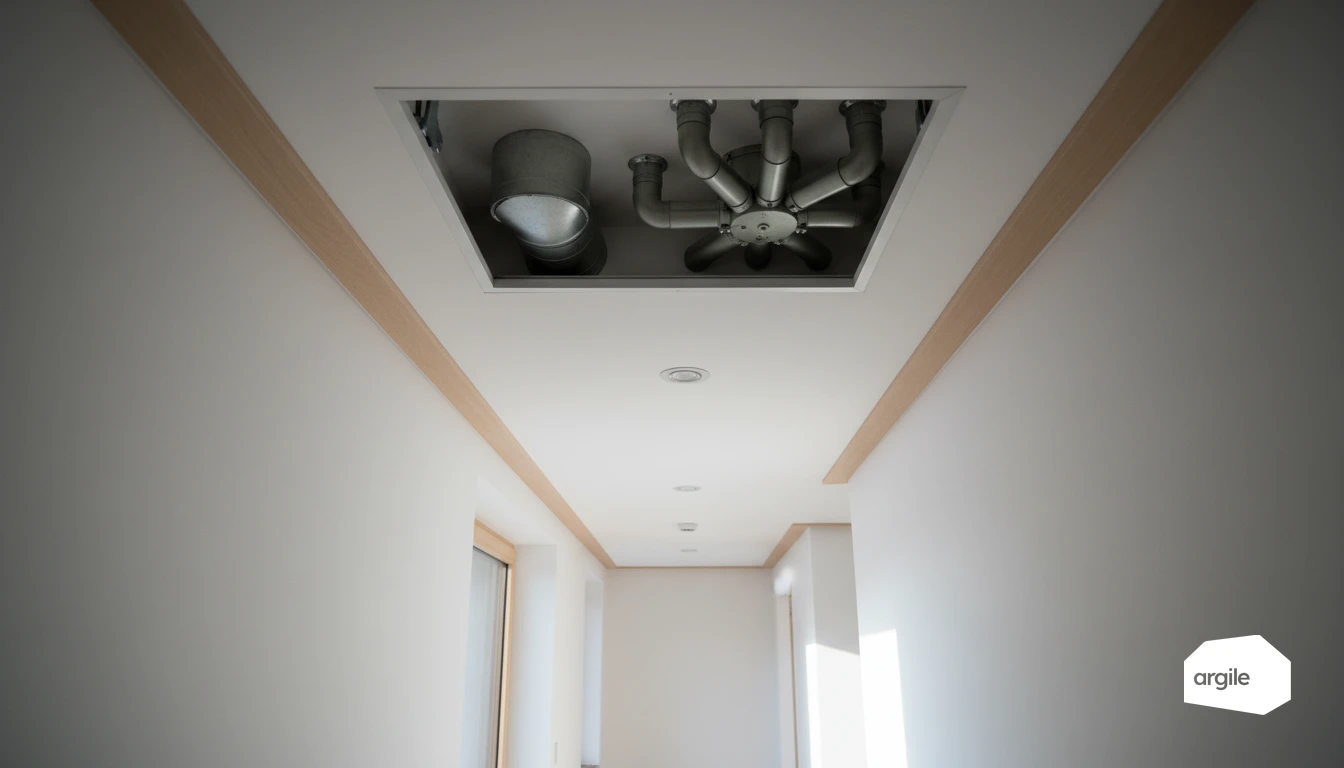
Before touching a single setting, walk the network. Ducts fixed at regular spacing, not crushed, at the diameters on the drawing. Joints pushed home and clips tightened, insulated duct everywhere in unheated volumes. On a heat-recovery system, check the condensate slope, the primed trap and accessible drainage. A network not validated before adjustment turns balancing into salvage, and salvage leaves marks on the report. The inventory of points to fix is set out in our article on duct airtightness in mechanical ventilation.
Checking the vents and theoretical flow rates: kitchen, wet rooms, WC, living rooms
Check that each vent is in the right room, clean, and that its adjustment range covers the flow required for that dwelling type. Compare against the sizing drawing before measuring, not after. On a heat-recovery system, label supply and extract room by room, a swapped sleeve in a bedroom being the most frequent error and the longest to track down once the ceilings are closed.
A reminder of the 2026 compliance points: certification, datasheets, manuals, and handover report
Installer certification in the right trade where subsidies are involved, datasheets for the unit, the vents and the ducts, up-to-date drawings and installation instructions including the NF DTU 68.3 rules, and a signed handover report with measured flow rates and any reservations. Since 2023, the AQC test certificates, sheet VMC2 for heat-recovery systems, replace the older COPREC sheets: they set out the tests to run before handover and the equipment required.
Carrying out the basic settings on a heat-recovery system: from power-on to speeds
Configuring the unit: speeds, modes, delays, and humidity sensing if present
After powering on, check the clock and the active mode. Set the permanent regime on the article 4 total flow, then the peak regime so that the article 3 kitchen flow stays reachable at any time, with a delay consistent with actual use. If the unit carries a humidity sensor, set a threshold and verify the switchover by simulating a rise in humidity rather than assuming it.
Adjusting the extract and supply vents: dampers, sleeves, and labelling
Open every adjustment component, then set vent by vent aiming at the flow rates on the drawing. Mark the position obtained on the sleeve and label each line. One DTU rule applies here and is regularly ignored: adding adjustment components that were not in the design to make up a pressure shortfall is not allowed. A network that does not hold is reworked, not compensated with an improvised damper.
Securing operation: rotation direction, noises, vibrations, and alarms
Check the fan rotation direction where access allows, then listen. Whistling, vibration or humming is the signature of a flow imbalance, a clogged filter, or a rigid fixing onto the structure. Check the filter alarms and the bypass operation. The causes and the levers for correcting them are set out in our article on mechanical ventilation noise.
Balancing the ventilation flow rates: a field method for a stable heat-recovery system
Measuring correctly: flow hood, pressure at the unit, and pressure losses
Measure vent by vent with a flow hood, filters clean and the network stabilised, and read the pressure available at the unit at the same time. An anemometer on its own stays treacherous at a vent outlet because of turbulence. Bends, lengths and silencers create pressure losses that explain why one room's flow checks out and the next one does not. The value each reading is compared against remains the room-by-room design figure, not the dwelling average. The instruments and the reading protocols are covered in our article on measuring ventilation flow rates.
Balancing extraction and supply: step by step by zone to avoid drift
Work zone by zone, starting with the least favoured branch and working back towards the shorter ones. Adjust the components shown on the drawing rather than the unit's speed, for as long as the adjustment range allows. After each correction, recheck two or three reference vents to catch the domino effect. On a heat-recovery system, finally check the cumulative balance between supply and extract, since an overall imbalance leaves the dwelling permanently pressurised or depressurised.
Validating the results: the numerical criteria, and where they come from
There is no single criterion but four families, drawn from different texts, and confusing them is how you end up with an indefensible report. The table below puts each value next to the text it comes from.
| What is measured | The criterion that applies | Where it comes from |
|---|---|---|
| Flow at each vent, supply and extract | stay within the flow range specified in the sizing, extreme vents included | NF DTU 68.3 |
| Regulatory compliance of the flow rate | measured flow increased by 15% at or above the required flow, and the sum of measured flows at or above the total required | RE2020 ventilation protocol |
| Allowed uncertainty on a flow measurement | 15% in total, measuring chain included | RE2020 ventilation protocol |
| Allowed uncertainty on a pressure measurement | the greater of the two, 10% or 5 Pa | RE2020 ventilation protocol |
| Negative pressure upstream of the extract fan, communal systems | deviation below 15 Pa from the design value | NF DTU 68.3 |
| Negative pressure downstream of the most favoured vent | deviation below 5 Pa | NF DTU 68.3 |
| Test deviation at the extreme vents | 30% at most | AQC test certificate, sheet VMC2 |
| Noise generated by the installation, at minimum flow | 30 dB(A) in main rooms, 35 dB(A) in the kitchen, vents included | order of 30 June 1999 |
The practical conclusion fits in one sentence: the percentages in circulation are measurement uncertainties, the values you can be held to on the network are in pascals, and the requirement most often forgotten is the acoustic one.
Airflow settings and air quality: optimising comfort and energy performance
Limiting over- and under-ventilation: what each one costs
Over-ventilation runs the fans higher on their curve, raises their consumption and degrades the heat-recovery balance. Under-ventilation leaves moisture and pollutants in the dwelling and exposes you on compliance with the article 3 table. The correct setting is held by measurement and documented, not judged by ear: the gap between the two is what separates an installation that is accepted from one that has to be reworked.
Optimising the bypass and the heat exchanger: summer and winter, defrosting, condensate
In winter, bypass closed to use the exchanger, and the defrost mode watched, reduced flow or pre-heating depending on the unit, because frost chokes the exchange and falsifies every flow reading. In summer, bypass open at night to discharge the thermal mass without reheating the incoming air, which stays marginal unless the facades are opened, as the achievable night purge flow rates show. On condensate, a continuous slope, a primed trap and accessible drainage, failing which the trap loses its seal and the unit pushes odours back.
Reducing noise: vents, ducts, silencers, and unit mounting
The 30 dB(A) requirement in a main room is lost on four points: vents closed too far and whistling, crushed ducts, tight bends, and a unit in rigid contact with the framing or a partition. Add a silencer at the unit outlet where network velocity is high, and mount the unit on anti-vibration feet with flexible sleeves at inlet and outlet. The check is made with a sound level meter, at the minimum flow setting.
Traceability and maintenance after commissioning: documents, client advice, and points to monitor
Formalising the commissioning: settings sheet, measured flow rates, photos, and labelling
A useful report carries values, not intentions. Flow measured at each vent, setting position recorded, pressure at the unit, noise level, method and instruments used, date and signature. Add three or four reference photos and the labelling of the unit and the main lines, captured as the job progresses from the job file itself rather than pieced together that evening. That document is the first thing asked for at an inspection, and the only one that protects you if a flow rate is disputed two years later.
Explaining maintenance: filters, access, frequency, and signs of clogging
Show the filters and how the hatches open without damaging the seals, and give an interval that can actually be kept. The signs of clogging are measurable before they are perceptible: noise rising, measured flow falling, condensation around the vents. A check-up visit after a few weeks of operation lets you observe the drift rather than learn about it through a complaint. The detail of the operations is in our article on mechanical ventilation maintenance.
Planning follow-up in 2026: check-up visit, seasonal adjustment, and routine troubleshooting
Offer the check-up visit in the original quote rather than after the fact: you re-verify flow rates, joint airtightness and condensate drainage, and adjust the seasonal setting if use has changed. In troubleshooting, the sequence is always the same, filters, vents, electrical supply, then pressure at the unit. Starting again from measurement avoids dismantling a network that has nothing wrong with it.