On an external wall insulation job, the singular points carry most of the risk of a claim: the insulation return at the reveal needs at least 4 cm, a drip cap under the window sill is mandatory, and the junction with the roof means carrying the continuity of the insulation through under the covering, failing which the thermal bridge left in place cancels part of the gain on the facade. On a block of flats, a fire-stop band is planned every two floors at the parapets. These details are surveyed facade by facade before ordering, because they are what fixes the take-off for accessories.
Preparing your external wall insulation project: identifying singular points and choosing solutions
Listing and mapping singular points before installation (sills, reveals, parapets, junctions)
Before starting external wall insulation, do a full survey, façade by façade. Identify window sills, reveals, slab edges, parapets, roof junctions, balconies, rainwater downpipes, ventilation grilles, and utility runs. Take photos, measure the overhangs, and prepare a façade plan with your thicknesses, to anticipate drip caps, copings, insulation returns, and airtightness continuity. From those photos, Argile's AI picks out the openings and works out the net façade areas, which settles straight away how many sills and reveals you have to treat. Façade contractor software then carries the linear metres of reveals, sills and lintels onto the quote lines.
| Singular point | What to survey before ordering | Accessories to plan for |
|---|---|---|
| Window sill | projection once the insulation is installed, slope, cracks | drip cap, added extension or new sill |
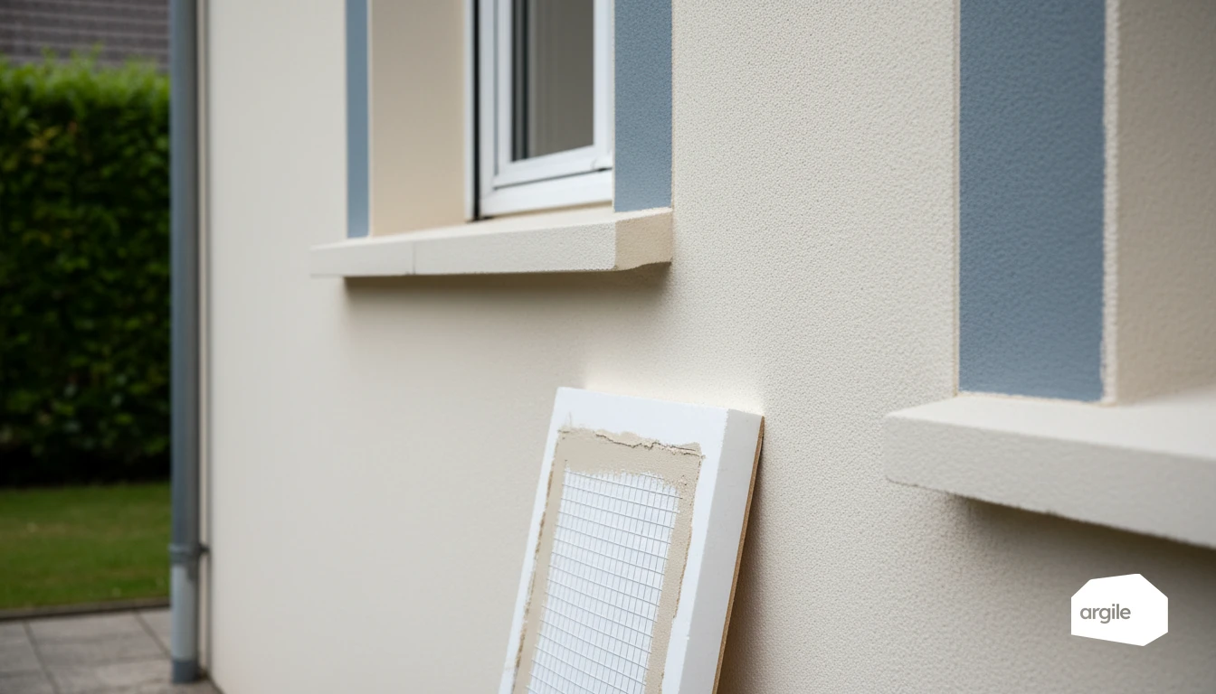
| Reveal and embrasure | insulation return of at least 4 cm, remaining daylight opening | 20 to 40 mm of insulation (PIR, aerogel), junction profile, compressible foam tape, jamb extenders |
| Window corner | exposure to impacts | corner bead, diagonal reinforcing mesh, reinforced render |
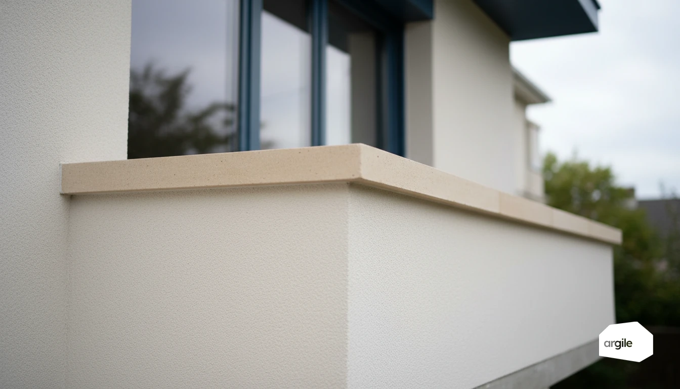
| Parapet and roof edge | available heights, water clearance, room left for the waterproofing upstand | coping with a drip groove and a drip cap, fire-stop band every two floors on a block of flats |
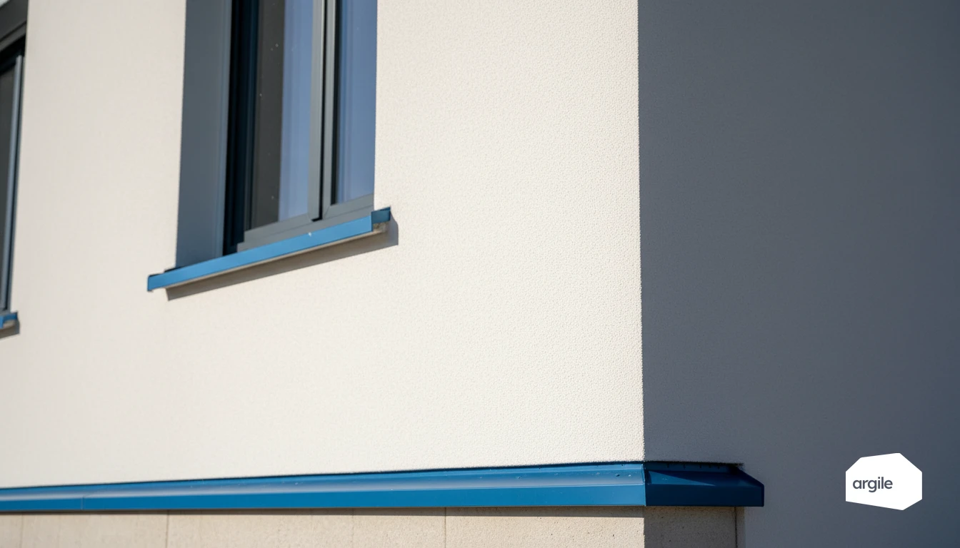
| Slab edge and base of façade | level of the substrate, rising water | starter track, base course protection, thermal break depending on the system |
| Penetration (grille, conduit, light fixture) | position of the utility runs | sleeve or collar, flexible joint, render repair |
Choosing the right external wall insulation system based on substrate and exposure (ETICS/render, cladding)
On a sound, flat masonry substrate, render-based ETICS is fast and handles thermal bridges well if the layout is clean. In highly exposed areas (driving rain, impacts, inconsistent substrates), ventilated cladding provides robust protection, provided you master the framing, the air gap, and the fixing points. Aim for a sound substrate and impact resistance suited to the site.
Checking DTU standards, technical approvals, DTA, and RGE requirements to secure installation in 2026
In 2026, secure the installation with the applicable DTU standards, the Technical Approvals, DTA, or ETA of the complete system (insulation, fixings, base coat, finish). Follow the manufacturer's prescriptions (mechanical fixing, bonding, profiles, treatment of singular points) and archive a site file (product data sheets, batches, photos), useful in case of an RGE, CEE, or MaPrimeRénov' inspection. To go further on requirements and risk management, see our article on preparing your projects and documents.
Window sills in external wall insulation: insulation continuity, sealing, and water drainage
Repairing existing sills or creating new ones: when to remove, when to keep
With external wall insulation, an existing sill is kept if it's sound, well bonded to the substrate, with sufficient projection once the insulation is installed. Remove or fully rebuild if the sill is cracked, has no slope, is too short (water runs down the façade), or prevents insulation continuity at the reveal. In that case, plan for a new sill or an added extension, sized to extend past the facing and receive a drip cap.
Treating the sill nose: drip edge, drip groove, slope, and insulation protection
Aim for a clear outward slope and a nose with a drip edge to break water runoff. A drip groove or an upstand piece on the joinery side limits water back-flow. Protect the insulation at the edge with a suitable profile and a closed underside, to prevent water entry and UV degradation before finishing.
Sealing and airtightness: tapes, membranes, drip caps, and junctions with the joinery
The sill-to-joinery junction is treated as a sensitive point. Use compatible sealing tapes (more airtight on the interior side, more vapour-open on the exterior side), supplemented by a membrane or a drip cap under the bottom rail. Take care with the returns in the reveals and the junction with the render, without any break in continuity, to keep the façade dry and durable.
Reveals and embrasures: limiting thermal bridges without losing daylight opening
Insulation thickness in reveals: balancing performance, constraints, and finishes
At reveals, every millimetre counts. Aim for a thickness that cuts the thermal bridge while keeping a comfortable opening. Often, 20 to 40 mm of rigid or thin insulation (PIR, aerogel type) is enough to treat the return without reducing daylight opening too much. Take care with adhesion, then a clean finish to avoid visible rework.
External wall insulation return and junctions with the frame: profiles, compressible foam tape, sealant, jamb extenders
With external wall insulation, the insulation return must reach the frame without a break. Use suitable junction profiles, a properly sized compressible foam tape, then a bead of compatible sealant. If the insulation adds thickness, jamb extenders ensure alignment between joinery, facing, and render, and avoid air gaps. To go further, see the impact of face-fixed, tunnel, or rebate installation on thermal bridges.
Reinforcement and protection: corner beads, mesh, reinforced renders to prevent cracks and impacts
Window corners take a beating. Install corner beads, a diagonal reinforcing mesh, then a continuous reinforced render. This limits micro-cracking, protects the insulation, and keeps the opening looking clean after a few winters.
Parapets and edges: managing external wall insulation on flat roofs and ensuring durability
Façade insulation continuity / waterproofing upstands: points of attention during installation
To maintain continuity of external wall insulation up to the flat roof, anticipate the junction with the waterproofing upstands. Plan for an insulation return over the parapet and a clear zone for the upstand.
Copings and drip caps: fixings, expansion, edge protection, and water drainage
Copings protect the edge and guide water outward. Choose profiles with a drip groove and a drip cap, fixed with clips or brackets. Leave expansion gaps and suitable junction pieces. Take care with the overlaps and joints to limit wind-driven water entry.
Heights, water clearance, and interfaces with the waterproofing: avoiding infiltration and disorders
Before installing the external wall insulation, check the available heights, the water clearance, the thresholds, and the drainage. The upstands must stay above the finished level of the terrace and its protections. Maintain the overflow outlets, avoid low points at the edges, and plan mechanical protection for the upstand. To go further on the insulation/waterproofing interface, see our article on external wall insulation and waterproofing on flat roofs.
Junctions and sensitive details: the singular points that make the difference in external wall insulation
Floor junctions, base courses, and the external wall insulation starter: thermal breaks, rails, protection against rising water
At the slab edge and the base of the façade, external wall insulation continuity is decided from the starter track onward. A properly leveled rail, base course protection, and a device limiting rising water. Also consider thermal bridge treatment through an insulation return or a thermal break, depending on the system.
Corners, expansion joints, and fixings: reinforcement, mechanical fixing, and movement management
At corners, reinforce the mesh with corner beads and reinforcing strips. Follow the existing expansion joints and those specified by the DTA. For fixings, follow the manufacturer's mechanical fixing plan. The right number and length prevent cracking and detachment.
Around penetrations (vents, conduits, light fixtures): sleeves, collars, and clean finishes
Every penetration is an open door to air and water. Use compatible sleeves or collars, then a continuous finish. A suitable flexible joint and a clean render repair around the added fittings improve sealing and long-term performance.
Checks before closing up the façade
- Insulation return at the reveal of at least 4 cm, unbroken all the way to the frame.
- Drip cap under the bottom rail of the sill, outward slope and a drip edge at the nose.
- No through-fixing in the waterproofed zone, clear zone kept for the upstand.
- Fire-stop band every two floors at the parapets on a block of flats.
- Starter track properly leveled, base course protected, rising water blocked.
- Corner beads, diagonal mesh and continuous reinforced render at window corners.
- Sleeve or collar on every penetration, flexible joint and a clean render repair.
- Manufacturer's mechanical fixing plan followed, expansion joints from the DTA respected.
- Dated photos of the singular points, product data sheets and batch numbers in the site file.