Boiler insert on an existing insert: what blocks the project and what you need to do instead
Why you cannot add a boiler unit to an insert that was not designed for it (overheating, hot spots, corrosion)
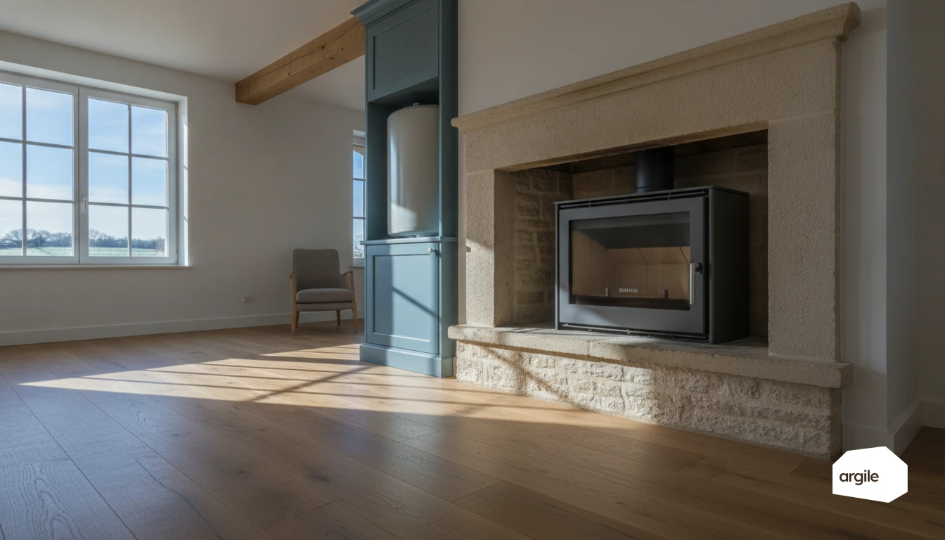
A boiler insert is not an “accessory”. The insert must be designed with a water jacket, flue gas paths, and a validated heat exchanger tested as part of the appliance. On a firebox that was not designed for this, you create stagnation zones. The result: hot spots, local boiling, and mechanical stress on the cast iron or steel. On the hydraulic side, cold return water and acidic condensate speed up corrosion if the appliance is not protected.
Adaptable kits: loss of appliance certification and insurance risk in the event of a claim
As soon as you modify the appliance, you move outside the scope of the manufacturer’s instructions and its declaration of conformity. In practice, certification and performance can no longer be relied on. In the event of a flue fire or overheating, the expert will look for the cause. A non-approved retrofit kit can shift liability to the installer, with a real risk that the insurer will challenge the claim.
The only proper route: replace it with a factory-made, certified, correctly sized boiler insert
The clean solution is a factory-made boiler insert, with markings and certified performance values. Size it based on useful water-side output, not total output. Then lock down the hydraulic safety devices (cold return protection, thermal dump, expansion) by following the manual and the applicable flue installation rules.
Choosing a boiler insert on the market: read the data sheet and target the right useful output
Water-side output / air-side output split: how to avoid an overheated room or lukewarm radiators
| Data to check on the data sheet | Unit | What to decide on site |
|---|---|---|
| Total useful output | kW | Compare with the calculated heating demand |
| Water-side output | kW | Basis for hydraulic sizing, not total output |
| Air-side output | kW | Limit it if the installation room is small |
| Water share (water/total) | % | The higher it is, the less you “load” the room |
A boiler insert is chosen first and foremost on its useful water-side output. If the air side dominates, the installation room will heat up quickly while the heating circuit remains lukewarm.
Check the certified performance values (efficiency, emissions): what you should find in the 2026 data sheet
Ask for a test report and a declaration of performance. On the data sheet, you should find the product standard, efficiency (useful and often seasonal), and emissions (CO, particulate matter, VOCs/OGCs, NOx) together with the measurement conditions. Without certified values, there are no grants, and it is hard to defend in an inspection.
Compatibility with the existing installation: radiators, underfloor heating, operating temperature
| Heat emitters to be supplied | Typical flow temperature | Key point to watch |
|---|---|---|
| “High-temperature” radiators | 60 to 75 °C | Check the heating body’s tolerance and the control strategy |
| “Low-temperature” radiators | 45 to 55 °C | Adjust weather compensation, avoid air-side overheating |
| Underfloor heating | 30 to 40 °C | Provide mixing, and safety devices independent of 230 V |
Check the manufacturer’s stated flow temperature range and the control strategy with the existing system, otherwise the boiler insert will short-cycle or condense on a cold return. To go further on emitter-side constraints, also see underfloor heating.
Hydraulics: sizing the buffer tank and protecting the appliance against cold return
Buffer tank required: sizing is based on water-side output and burn duration, not total output
Content under review against official sources (ADEME, Ministry) before publication.
Thermostatic loading valve: securing the temperature rise and avoiding cold return
Content under review against official sources (ADEME, Ministry) before publication.
Connection to the existing circuit: standard schematics (heating only, with domestic hot water, with boiler/heat pump as backup)
Content under review against official sources (ADEME, Ministry) before publication. In the meantime, you can rely on standard schematics to validate the possible arrangements.
Securing the installation: overheating, pressure, power cuts, and essential components
Thermal safety device independent of the electrical supply: heat dissipation in the event of overheating
On a water-based appliance (factory-made boiler insert, not an added boiler insert retrofit), provide a heat dissipation path that does not rely on electricity. The standard solution is a bulb-operated thermal valve, supplied with mains water, which opens into a cooling coil and discharges to drain. The goal: avoid runaway overheating if the circulator stops.
Expansion vessel, safety valve, air vents and pressure gauge: key points in a closed circuit
| Component | Usual setting | Unit |
|---|---|---|
| Heating safety valve | 3 | bar |
| Cold fill pressure | 1.0 to 1.5 | bar |
| Thermal valve trip temperature | 95 | °C |
Size the expansion vessel according to the total water volume and temperatures. Install a readable pressure gauge, air vents at high points, and a safety valve close to the exchanger, with no isolation valve in between.
Installation rules and checks: reducing risks (sludge, air, valve setting, tests before recommissioning)
- Flush the system if you are working on an existing circuit, then fit a sludge pot and filtration.
- Fully bleed the system, check safety valve settings and vessel pre-charge.
- Carry out a leak test and a monitored temperature ramp-up, with flow and return thermometers and flow-rate checks.
Flue, combustion air supply and grants: the checks that prevent nasty surprises
Flue: lining, diameter, airtightness and sweeping before commissioning
Before promising a hydraulic connection or talking about a boiler insert, start with the flue. Check that it is clear, that the liner is suitable for wood combustion, that the effective cross-section matches the manufacturer’s instructions, and that the joints are sound. Have a recent sweep carried out or documented, then check the route for airtightness. Any issue with the flue blocks commissioning and puts the site liability front and centre.
Combustion air supply: sizing and the case of tighter homes after renovation
Air is the weak point in renovation work. Size the air supply according to the manual’s value. Identify the MVHR/ventilation system, existing air inlets, door undercuts, and the risk of negative pressure. In a reinforced envelope, provide a dedicated direct air supply and test the draught under real ventilation conditions. The aim is combustion stability, not improvisation.
Grant eligibility in 2026: certified performance to prove + alternative route if the client wants automation (link to pellet stove product page)
In 2026, eligibility for MaPrimeRénov’ and CEE schemes depends on certified performance and a qualified installer. Ask for proof before quoting: exact reference, certification, and test data (efficiency, emissions) matching the installed model. If the client wants automation and simpler control, steer them instead toward a pellet stove suited to the existing system. For the conditions and supporting documents expected, also see the 2026 conditions and rates.