Safety valve group: a regulatory requirement and a sensitive inspection point
Why the safety valve group is mandatory on a DHW tank (risks and liabilities)
On a domestic hot water tank, the safety valve group limits overpressure caused by thermal expansion during heating. Without protection, the cylinder and the cold-water network can build up pressure, with a risk of rupture, scalding and water damage. In the event of a problem, your contractual liability and the ten-year structural warranty may be engaged.
| Setting pressure (bar) | Valve between group and tank (yes/no) | Visible discharge to waste (yes/no) |
|---|---|---|
| 7 | no | yes |
What inspectors check on site in 2026 (component, positioning, accessibility)
In 2026, the key issue is installation compliance. The group is fitted on the cold-water inlet, as close as possible to the tank, with access to the lever and inspection plug. Inspectors look for no valve in between, a discharge connected with an air gap, and a flow path that can be traced all the way to the trap.
Scale, the silent trap
Limescale can jam the check valve or relief valve. Plan for descaling or documented periodic replacement, otherwise pressure can rise without warning.
On site, check
- EF identification and installation direction.
- No isolating device between tank and group.
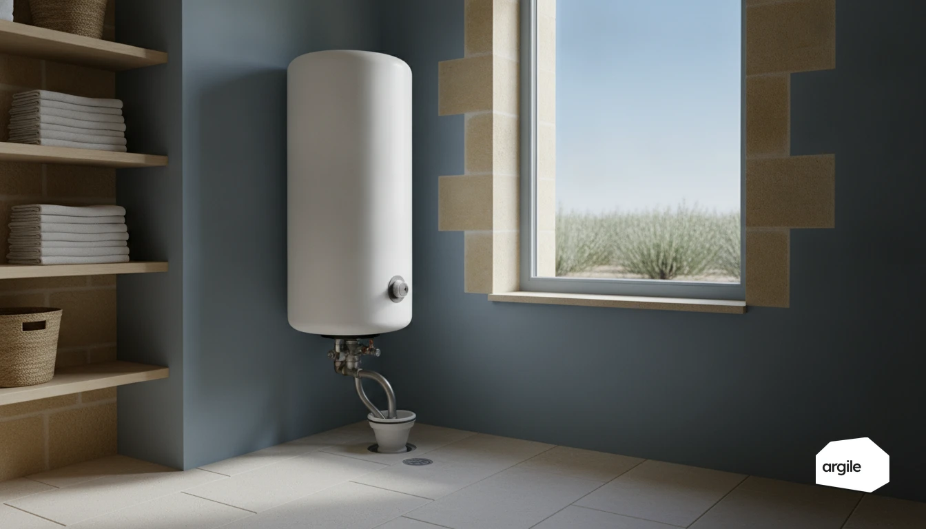
- Discharge that cannot be obstructed, visible, with trap.
- Accessibility for testing and replacement.
Differences to know: safety valve group on electric tank, heat pump water heater, boiler-linked tank
Electric tank and heat pump water heater. Same logic on the cold-water inlet. The heat pump version adds a separate condensate drain from the safety valve group discharge. Boiler-linked tank. Depending on the scheme, protection may rely on a dedicated relief valve. Keep the discharge visible to waste and show the devices on your drawings and quotation. To further secure your file from a liability standpoint, also consider site handover and its quality checkpoints.
Setting pressure, pressure and DHW tank relief valve: understand it to avoid overpressure
Safety valve group setting pressure: expected value and consistency with the network
| Check point | Target value | Unit |
|---|---|---|
| Safety valve group relief setting | 7 | bar |
| Downstream pressure reducer pressure (cold, static) | 3 | bar |
On a DHW tank, a 7 bar setting is not optional. Check the actual network pressure first, then match the pressure reducing valve and accessories. Between the cold-water inlet and the tank, avoid any valve that could isolate the relief device.
Symptoms of poor adjustment: continuous discharge, water hammer, tripping
A continuous discharge at the drain, water hammer when taps are closed, or frequent tripping during heating often indicate excessive upstream pressure, an unstable pressure reducing valve, or a scaled-up safety valve group. The discharge must remain visible, with a trap, so you can quickly spot abnormal flow.
Common cases: inlet pressure too high, role of the pressure reducing valve and domestic expansion vessel
If inlet pressure varies significantly, install a properly set pressure reducing valve and check its dynamic performance. Add a domestic expansion vessel on the cold-water side, downstream of the pressure reducing valve, pre-charged to the measured static pressure. Plan anti-scale maintenance. A blocked safety valve lets pressure rise without warning.
No isolation valve between the tank safety valve group and the tank: the rule that prevents claims
Why an isolation valve between the group and the tank is prohibited (pressurisation with no escape path)
Between the tank cold-water inlet and the safety valve group, no valve belongs there. If you isolate that section, you can pressurise the cylinder with no escape path. During heating, expansion can no longer be relieved through the valve. The result: overpressure, leaks at joints, deformation of the tapping, or even rupture. The relief valve only works if it is directly connected to the tank.
Principle diagram: where to place the valve if you need to intervene
If you need to remove the group, place the shut-off valve on the cold-water supply, upstream of the group, with a drain point. The arrangement remains: cold-water network, valve, (pressure reducing valve if required), group, tank. The safety device stays as close as possible to the tank tapping, with no intermediate accessory. For more on standard arrangements, rely on a basic hydraulic schematic.
Typical site mistakes: flexible hoses, fittings, check valves and assemblies that close “by accident”
- Braided hose with an integrated check valve on the tank side.
- Union fitting with a displaced seal that blocks the passage.
- Pollution control valve or non-return valve fitted between the group and the tank.
- Convenient quarter-turn valve added during a replacement.
Visible discharge and safety valve group trap: drain correctly without hiding the warning signs
Normal discharge from the safety valve group: when it is acceptable and when it is not
A drip-drip from the safety valve group during the heating phase is expected. It reflects tank expansion and discharge at service pressure. On the other hand, continuous discharge when not heating, a steady trickle, or a significant flow should alert you. You do not try to “make it disappear”. You deal with the cause. On site, check upstream pressure, the seat condition and limescale buildup.
Safety valve group trap: purpose, selection and installation to avoid odours and backflow
The dedicated trap prevents odour backflow and limits reverse flow towards the safety valve group outlet. Choose a removable, accessible model with an inspection plug. Install it without mechanical stress on the group outlet, and keep an observation area upstream so you can immediately see abnormal discharge.
Connection to waste: slope, diameter, air gap and items to avoid
Connect the discharge to a gravity drain with a regular slope and a diameter compatible with the trap. Provide an air gap or a visible funnel before the drain. Do not use: a pipe embedded in a partition, backfall, a flexible hose that sags, a connection to a saturated or unvented drain.
Scale: the trap that jams the safety valve group and makes pressure rise without warning
How scale seizes the DHW tank relief valve (warning signs on site)
In hard water, scale deposits on the valve seat and can stick the mechanism of the safety valve group. As a result, expansion is no longer discharged as heating continues. Pressure rises in the cylinder, with no obvious sign, until a leak at a joint, seepage at a seal, or a late and sudden opening.
- No drip during a full heating cycle.
- Stiff operation or incomplete return after testing.
- Whitened valve nose. Deposits in the discharge.
Maintenance and operation: best practices to explain to the customer (and record)
At the end of the job, operate the valve firmly and check for visible discharge at waste. Explain the periodic operation recommended by the manufacturer, then record it in your file. Date, condition of the lever, presence of deposits, and condition of the trap. That is what protects you if the issue comes back.
When to replace rather than “descale”: 2026 criteria, service life and equipment choice
Once the mechanism starts to seize, “descaling” rarely lasts. In practice, replacement is better than patching it up. To frame the decision for the customer, also rely on the service life of water heaters (use, hard water, end-of-life signs).
| Criterion | Value | Decision |
|---|---|---|
| Age in hard water | > 5 years | Replace |
| Operation | Stiff or stuck | Replace |
| Discharge | Absent then sudden | Replace |