Real savings: what gains can you measure with a connected thermostatic valve head?
Typical on-site range: from a few percent to a meaningful gain, depending on the dwelling
On already well-controlled hydronic systems, a connected thermostatic valve head often delivers a modest measured gain, typically a few percent. The improvement becomes much more visible when you start from no control at all, regular overheating, or “forgotten” rooms (bedrooms, home office). The right field reflex is to measure before and after in kWh corrected for heating degree-days, over a comparable period.
What changes the savings: temperature spread between rooms, occupancy habits, and setpoint temperature
The first lever is the temperature difference between rooms. The more zones you can lower without discomfort, the greater the room for savings. Then come occupancy schedules, the generator’s responsiveness, and the average setpoint. A lasting setback matters more than any “smart mode.” Without balancing and proper flow, the head controls poorly and the savings are diluted.
Do not promise “X %” without context: how to present a realistic gain to the customer
Present a range, with conditions. Example: “We are aiming for a gain in the order of a few percent, and more if we reduce overheating and genuinely lower certain rooms.” On the quote, tie the gain to simple assumptions (setpoints, schedules, reference degree-days) and note the prerequisites: compatible valve bodies, balancing, venting, and verification of supply/return ΔT. That is your safety net if the claim is challenged.
Room-by-room control: when it works… and when it does not control anything
Room-by-room control principle: what the connected thermostatic valve head actually controls
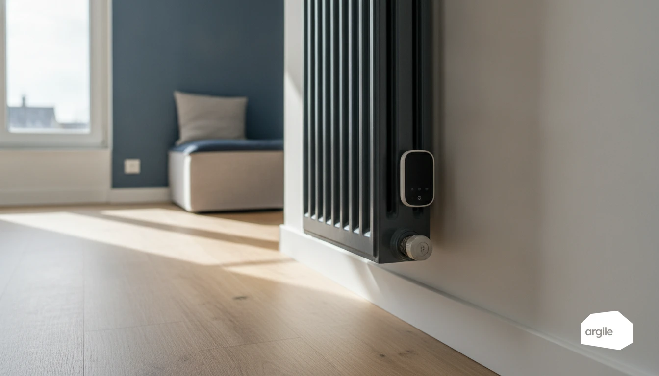
A connected thermostatic valve head controls the opening of the radiator valve to maintain a setpoint temperature measured in the room. It does not control water temperature, the boiler, or the circulator. Its effectiveness therefore depends on the compatibility of the valve body (stroke, closing direction, adapter) and on the radiator being able to modulate, not just switch on and off.
The blocking point: hydraulic balancing and flow, otherwise the valve has no effect
Without hydraulic balancing, you can end up with rooms that “hog” all the flow and others that are starved of water. In that case, the head opens but the radiator stays lukewarm. Or it closes, but the flow is diverted elsewhere and the room never stabilizes. Before judging the control, check circulation, return valve settings, and whether flow rates make sense room by room.
Typical cases where the result disappoints: oversized radiators, circulation defects, already effective heads
The gains are real, but they first depend on the setpoint gap between rooms. If every room is at the same setting, you are not creating useful control. If the radiators are very powerful with a water law that is too high, the control becomes on/off.
| Site condition | Measured heating gain (%) |
|---|---|
| Small setpoint differences and an already stable system | 0 to 3 |
| Real setpoint differences and a balanced network | 5 to 15 |
| Hydraulic imbalance, flow defect, underfed radiator | 0 |
Compatibility and installation: check the valve body before selling the solution
Identifying the valve body: models, threads, adapters, and the limits of supplied rings
Before proposing a connected thermostatic valve head, identify the valve body. Most heads on the market fit M30 x 1.5. Danfoss bodies (RA, RAV, RAVL) and some M28 x 1.5 models require an adapter. The “universal” rings often supplied only cover a limited range and do not compensate for a damaged thread or an out-of-tolerance nut.
| Connection (mm) | Common family | Key point |
|---|---|---|
| M30 x 1.5 | Standard European bodies | Direct fit if the seating surface is clean |
| M28 x 1.5 | Some compact bodies | Dedicated adapter, watch the stroke |
| RA / RAV / RAVL | Danfoss | Specific adapter, correct bearing on the spindle |
Installation traps: spindle travel, leaks, seizing, positioning, and flow direction
The real issue is the spindle travel. If the adapter pushes too early, the valve remains throttled. Too little, and the control never closes. Also look for sealing-face leaks, spindle seizure, and misalignment that puts the actuator on an angle. On the installation side, avoid fitting the head in a low position on the radiator, and check the flow direction where the body requires it.
Jobsite checklist: items to record before ordering to avoid returns and disputes
- Brand, body reference, and a clear photo of the thread and spindle.
- Measured connection type, thread condition, presence of a spacer.
- Free movement of the spindle, with no hard point.
- Available space around the radiator, access, collision risk.
- Existing balancing, return valve settings, differential pressure.
Radiator programming and scenarios: what the “connected” feature really brings
Radiator programming: time slots, night setback, and control of lightly used rooms
The gain does not come from a magic percentage. It comes from a real setpoint difference between rooms, maintained over time. With room-by-room time schedules, you secure a setback at night and avoid keeping bedrooms or offices at the same level as the day zone. During the technical visit, note the thermal inertia (cast iron, steel, underfloor), and the hydraulic balancing. Without coherent flow rates, the control will not stabilize.
Connected thermostatic valve network: the role of the gateway, connectivity, and service continuity
A connected thermostatic valve head is only as good as the network behind it. The gateway links the heads (often via local radio) to the app. Require a local mode in case internet is cut off, and check valve body compatibility (thread, adapters, stem travel) before quoting.
Useful settings in 2026: constraints to set (inertia, restarts, valve noise, batteries)
In setup, limit overly frequent setpoint changes. On a boiler or a heat pump, too many restarts reduce efficiency and wear the valve. Set a restart delay, accept a realistic control band, and plan battery maintenance (alerts, route, stock). To go further, see how to adapt time schedules to everyday use.
Contractor method: price, explain, and secure the result for the customer
Before/after: measure properly (temperatures, boiler cycles, consumption) and over what duration
Set a baseline before the connected thermostatic valve head is installed. Record setpoints by room, measured temperatures, and a heating indicator (run time or cycles). Align the periods with comparable weather, or correct using DJU.
| Indicator | Source | Minimum duration (days) |
|---|---|---|
| Room temperatures | probe, logger | 7 |
| Boiler cycles or hours | meter, control system | 14 |
| Gas or electricity use | bill, remote meter reading | 30 |
Honest sales pitch: savings from avoided “overheating,” not from any connected magic
The gain mainly comes from avoiding temperature differences between rooms, so from the actual control setting. Without hydraulic balancing and coherent flow rates, the head only “closes too late.” Sell control, not a percentage.
When to recommend something else: pipe insulation, insulation, central control, standard head, or heating intervention
- Small temperature difference between rooms, no measurable overheating.
- Incompatible or seized valve body. Replace before fitting equipment.
- Unbalanced network. Plan balancing, venting, pump adjustment.
- Heavy losses in distribution or through the building fabric. Prioritize pipe insulation and insulation.