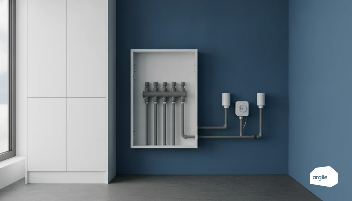
Understanding what your heating energy meter measures (and what it does not measure)
The three key components: flow meter, pair of temperature sensors and calculator
A heating energy meter is a thermal energy meter. It calculates the energy transferred to the circuit by combining a measured flow rate (flow meter) and a temperature difference (matched supply and return sensors). The calculator integrates the fluid and the metrological parameters. Without consistency between flow direction, sensor position and parameter settings, the measurement is technically usable, but not billable.
What you read on the display: energy (kWh/MWh), volume, temperatures, ΔT
| Data | Unit | Professional interpretation |
|---|---|---|
| Cumulative energy | kWh, MWh | Basis for cost allocation |
| Volume | m³ | Hydraulic consistency check |
| Supply, return temperature | °C | Monitoring control and balancing |
| ΔT | K | Exchange and drift indicator |
Thermal energy meter vs heat cost allocator: do not confuse the uses
A thermal energy meter measures energy on a hydraulic network. A heat cost allocator, on the other hand, estimates a share of consumption from a radiator. It does not measure energy in kWh. In horizontal distribution, you can aim for apartment-by-apartment metering. In vertical riser systems, heat cost allocators often remain the only option, except for exemptions provided for under the individualisation framework.
Choosing the right heating energy meter for your installation
Diameter, flow range, pressure loss: size it without throttling the system
A heating energy meter is selected based on the design values. If the actual flow rate remains too low or too high compared with the flow meter range, you lose accuracy and increase pressure loss.
| Parameter | Unit | What to check | Watch-out |
|---|---|---|---|
| Nominal diameter (DN) | mm | Drawings, on-site identification | DN must match design flow |
| Nominal flow rate (Qp) | m³/h | Calculation note, meter data sheet | Operation should be mostly around Qp |
| Maximum flow rate (Qmax) | m³/h | Meter data sheet | Avoid saturation in steady operation |
| Pressure loss at Qp (Δp) | kPa | Meter data sheet | Compatible with pump and balancing |
| Location, mounting direction | - | Hydraulic schematic | Arrow, supply or return, matched sensors |
Metrological class and compliance (EN 1434 / regulatory requirements): get it right from the purchase stage
For re-invoicing, choose equipment that is MID compliant (MI-004) and assessed according to EN 1434. The accuracy class (1, 2, 3) should be chosen according to the application. Keep the declaration of conformity, CE marking and sealing elements. This is your evidence file in case of a dispute.
Reading transmission (M-Bus, radio) and compatibility: anticipate operation by the manager
Validate the reading protocol with the manager. Wired M-Bus, wM-Bus radio or a proprietary solution do not always mix. Check concentrator integration, time stamping, index export and useful alarms (reversed sensors, zero flow). Good compatibility avoids unnecessary site visits.
Installing the thermal energy meter without mistakes: the step that secures the billing
Supply or return: choose the right section according to the hydraulic configuration
A heating energy meter is installed where the circuit is clear. In direct production, either the supply or the return works, provided both sensors correctly read the supply and return of the same circuit. In the presence of a 3-way valve or mixing loop, place the meter on the section that actually frames the emitter (before or after mixing, depending on what you bill). Avoid branch take-offs and bypasses between the two measurement points.
Flow meter: mounting direction, position, straight lengths and on-site pitfalls that distort the reading
Respect the flow arrow, the position (horizontal or vertical depending on the manufacturer’s instructions) and the upstream/downstream straight lengths. An upside-down installation, a partially closed valve, a pump that is too close or an air pocket make the measurement unusable. Plan for filtration, venting and access for maintenance. At commissioning, record instantaneous flow, temperatures and the totalizer.
Temperature sensors: pairing, location (pockets/immersion) and installation rules for reliable measurement
The sensors come as a matched pair. Do not swap them. Install them in suitable sensor pockets or by immersion, in areas with stabilized temperature, with good thermal contact and insulation of the sensor pocket. Seal and trace the identification of the sensors and the calculator to keep a consistent measurement chain.
Commissioning, reading and checking the readings day to day
Commissioning and sealing: what you must check before handing the job back over
Before signing the completion slip, validate the sensor pairing (numbers, positions, insulation of sensor pockets), the flow direction on the flow meter, and the section actually instrumented (supply or return). Record the initial index (energy, volume), date and time. Have the seals installed and logged, then archive photos, serial numbers and settings (units, constants, radio address).
- Presence of a clean filter upstream and operational isolation valves.
- No visible bubbles and venting completed before stabilization.
- Clear labelling on the riser or the instrumented branch.
Consistency checks: compare ΔT, flow and energy to detect an inversion or sensor fault
On a heating energy meter, check physical consistency. A negative or unstable ΔT often points to reversed sensors, poor thermal contact or a non-matched sensor. Also verify that energy increases when flow is non-zero and that the circuit is under load.
| Quantity | Unit | Quick check | Warning sign |
|---|---|---|---|
| ΔT | K | Stable sign, plausible value | ΔT < 0 |
| Flow | m³/h | Consistent with valve opening | 0 with heat demand |
| Estimated power | kW | 1.163 × flow × ΔT | Clear mismatch with display |
Handling faults: air, fouling, stuck sensor, drift and corrective actions
If a fault occurs, prioritize a short, documented intervention, and freeze billing if the measurement is no longer reliable. Deal with the hydraulics first (venting, filter, sludge), then the measurement chain (sensors, wiring, calculator). Document the cause, the affected period and the return to normal.
- Air and microbubbles: venting, pressure check, high point.
- Fouling: filter cleaning, flushing, pressure loss check.
- Drift: metrological check, sensor or flow meter replacement.
Individualizing heating costs in collective systems: when to install apartment meters, when to use heat cost allocators (2026 framework)
Horizontal distribution: conditions for apartment-level metering with a heating energy meter
In horizontal distribution, an apartment-level metering device is usually possible: a single measurement point on the apartment heating supply, with a heating energy meter, isolation valves and access for reading and maintenance. Check the flow meter mounting direction and the pairing of the sensors on the supply and return.
Vertical risers: why heat cost allocators often remain the only option (and their limits)
In vertical risers, apartment-by-apartment metering would require grouping the risers or creating a manifold, which is rarely realistic in refurbishment. Heat cost allocators on radiators remain the common option, but they provide a proportional allocation and not an energy value in kWh. Hydraulic balancing and correct parameter setting are non-negotiable.
Exemptions, thresholds and 2026 deadlines: points to check in the current texts before publication and works
Before quoting, confirm the applicable thresholds, exemptions (technical impossibility, disproportionate cost) and deadlines for the building, in the Energy Code and the current decrees. Document the justification in the project file (feasibility note, assumptions, network drawings, readings).