Understanding the heat meter and its measuring principle
Definition: measuring thermal energy from flow rate and temperature difference
A heat meter measures the energy exchanged in a hydronic circuit. The principle is simple. You measure a flow rate (volume or mass) and calculate energy from the temperature difference between supply and return. The calculator integrates these measurements over time and outputs an energy value (often in kWh) that can be used for cost allocation, operational monitoring, or dispute resolution.
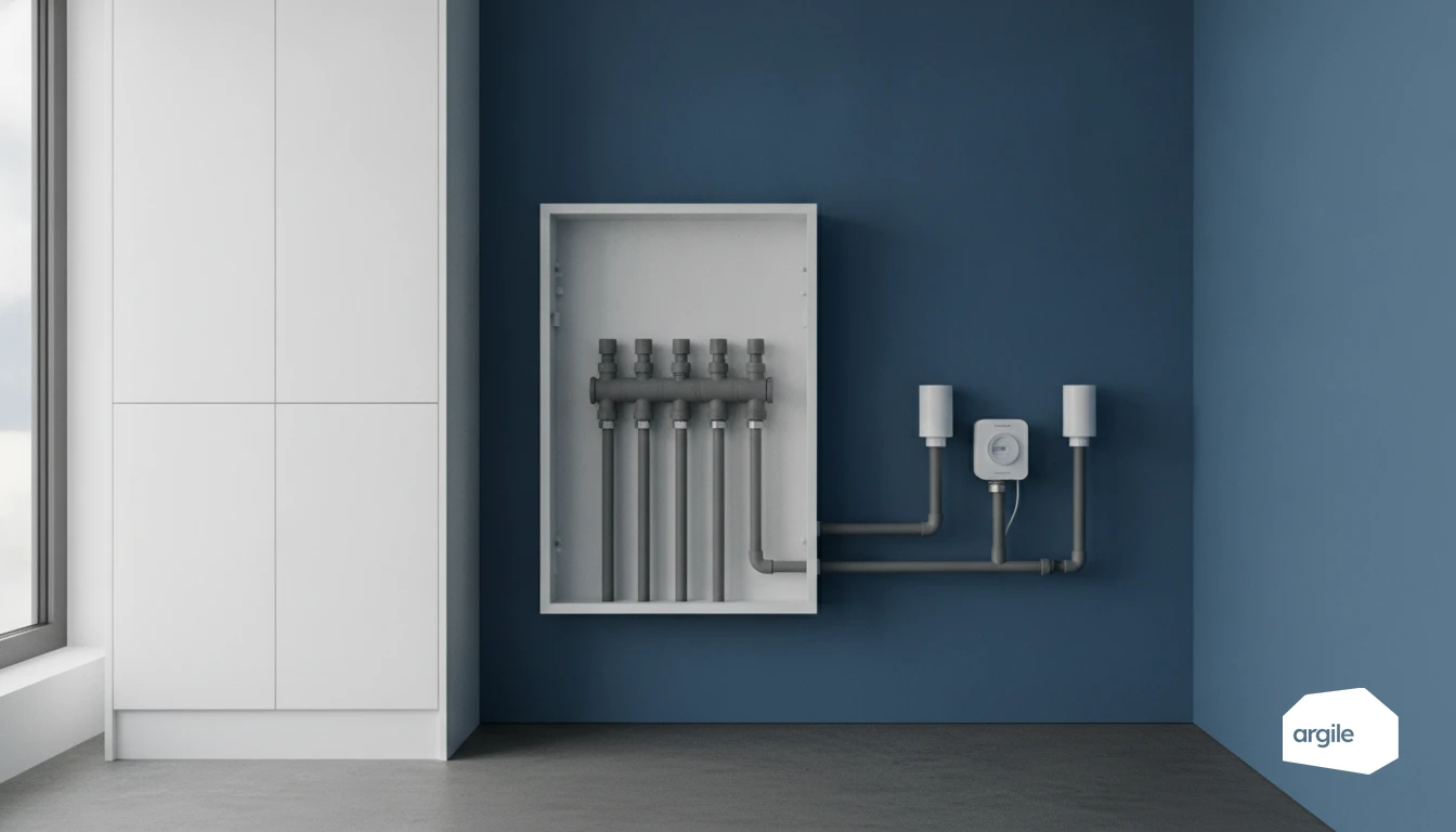
The three essential components: flow meter, matched probes, calculator
The flow meter (turbine, ultrasonic, or electromagnetic depending on the model) provides the volumetric basis. The pair of matched temperature probes is installed on the supply and return, with the same metrological chain. The calculator applies the fluid constants, stores the indexes, manages timestamping, and receives the required seals.
Where it is used in practice: boiler plant, substations, apartments in collective housing
In the boiler plant, it is used to meter total production or network supply. In a substation, it tracks the energy delivered to a building or a use (heating, domestic hot water). In collective housing, it is found at riser base or on a loop, when the metering scheme aims for robust, enforceable allocation.
Do not confuse a heat meter with a heating cost allocator
What a cost allocator measures (and does not measure): an index, not energy
A heating cost allocator is attached to the emitter. It records an index linked to the radiator temperature regime, corrected by coefficients (type of emitter, output, installation). It does not measure flow, supply-return difference, or energy in kWh. A heat meter, on the other hand, calculates energy from flow rate and ΔT on the network.
Why the distinction matters for cost allocation in collective housing
In collective buildings, the individual metering rules distinguish energy metering from allocation. A cost allocator is used to distribute a “heating” share between units, but it does not replace enforceable energy metering. Mixing the two creates the risk of a contestable allocation key, especially if correction factors and installation conditions have not been documented.
How to explain it clearly to the property manager, design office, and occupants
In technical notes and quotations, name the devices and the intended use. Write “allocation” for cost allocators, “energy metering” for heat meters. Specify the location, model, and installation rules (height, direction, sealing). And state the expected output. Allocation units on one side, kWh on the other.
Choosing the right heat meter: checks before ordering
Type approval: European metrology directive and 2026 requirements to check in the datasheet
Before ordering a heat meter, ask for the EU Declaration of Conformity and the EU Type Examination Certificate. Check the reference to Directive 2014/32/EU (MID), Annex MI-004, and the CE marking with M, the year, and the notified body. In 2026, also check the calculator version and the installation conditions validated in the instructions (position, direction, temperature ranges).
Accuracy classes and uses: choose the right level of requirement for the project
EN 1434 distinguishes classes 1, 2, and 3. In a collective boiler plant with recharging, class 2 is often a good balance. Class 1 is justified when you want a very solid contractual framework or want to limit dispute risk. Align the requirement across the whole system: flow meter, probes, and calculator.
Hydraulic compatibility: flow rate, pressure drop, and installation constraints
| Q3 (m³/h) | Pressure drop (kPa) | DN (mm) | Upstream straight length (xDN) | Downstream straight length (xDN) | Position (supply or return) |
|---|---|---|---|---|---|
| To be checked in the instructions | To be checked in the instructions | To be checked in the instructions | To be checked in the instructions | To be checked in the instructions | According to manufacturer |
Check the operating flow rate and allowable pressure drop. Respect straight lengths, avoid nearby disturbances (elbows, pumps), and confirm installation of matched and sealable probes. Then order a complete kit with the same references and cable lengths.
Installing a heat meter without falling into the usual site traps
Upstream/downstream straight lengths: follow the recommendations to avoid measurement errors
Before tightening the first fitting, identify the heat meter technology (ultrasonic, turbine, electromagnetic) and open the manual. Errors often come from flow disturbance. Keep the required straight pipe section, with no elbow, valve, pump, or reducer nearby. If space is tight, plan a conditioning section or another location.
Mounting direction and supply/return position: follow the manual, not habits
Respect the flow arrow on the body. Also check the permitted orientation (horizontal, vertical) and access to the calculator for reading and meter collection. Supply or return: there is no universal trade rule. Some models require return to limit temperatures and simplify balancing. Others accept both. Follow the manual and note the exact location in the handover file.
Matched probes, pairing, and sealing: securing the measuring chain
Temperature probes come as a matched pair. Do not swap them between meters. Install them in suitable pockets, at the correct depth, with thermal paste if specified. Check ΔT consistency during filling. Finish by sealing the intended points (probes, calculator, flow meter) and recording the serial numbers. Add dated photos and you will sleep easier if the installation is challenged.
Securing the measurement and limiting disputes: good commissioning practice
Errors that make the measurement unusable: unmatched probes, ignored straight lengths
On a heat meter, the pair of temperature probes must remain matched (same references, correct installation, sealing if provided). Mixing probes or reversing the wiring is enough to make the measuring chain contestable. The same applies hydraulically. If the upstream and downstream straight lengths stated in the manual are not respected, the flow meter may fall outside its accuracy range. In a dispute, that is often where things break down.
Acceptance checks: temperature consistency, leak tightness, calculator settings
- Read supply and return. Check that the values make physical sense (supply higher than return, stable difference).
- Check the leak tightness of tappings and pockets after venting. For further work, you can rely on a network pressure test before filling.
- Validate the calculator settings. Nominal diameter, pulse constant, units, flow direction, date, and starting index.
Useful traceability in case of dispute: identification, seals, photos, and archived documents
Clearly identify the serial number, installation point (supply or return), and flow direction. Apply the required seals and photograph the installation, labels, probe connections, and display at commissioning. Archive the declaration of conformity, type approval, configuration sheet, and acceptance report. It is your safety net when operations demand accountability.