The U-value of a wall is the heat flow through one square metre of the element for a 1 kelvin temperature difference between the two environments, expressed in W/(m².K). It is obtained from U = 1 / Rtotal, where Rtotal adds up the resistances of every layer plus the two surface resistances defined by ISO 6946, 0.13 on the inside and 0.04 on the outside for an external wall. It is the inverse of a resistance: the 0.30 W/(m².K) that Approved Document L sets as the retrofit value for an internally insulated wall corresponds to a total resistance of about 3.3 m².K/W. Take care not to confuse this opaque-element U with the whole-window Uw or with the linear U of a lagged pipe: these are three distinct quantities, and two of them do not even share the same unit.
U-value and the U-coefficient: what you need to know about a wall's thermal behaviour
Wall U-value: simple definition and units (W/m²·K)
The U-value (or U-coefficient) indicates how much heat passes through a wall, per 1 m² and per 1 degree of difference between indoors and outdoors. The unit is W/m²·K. The lower the U, the more your insulation limits heat loss.
What heat transfer actually measures: losses, comfort, condensation
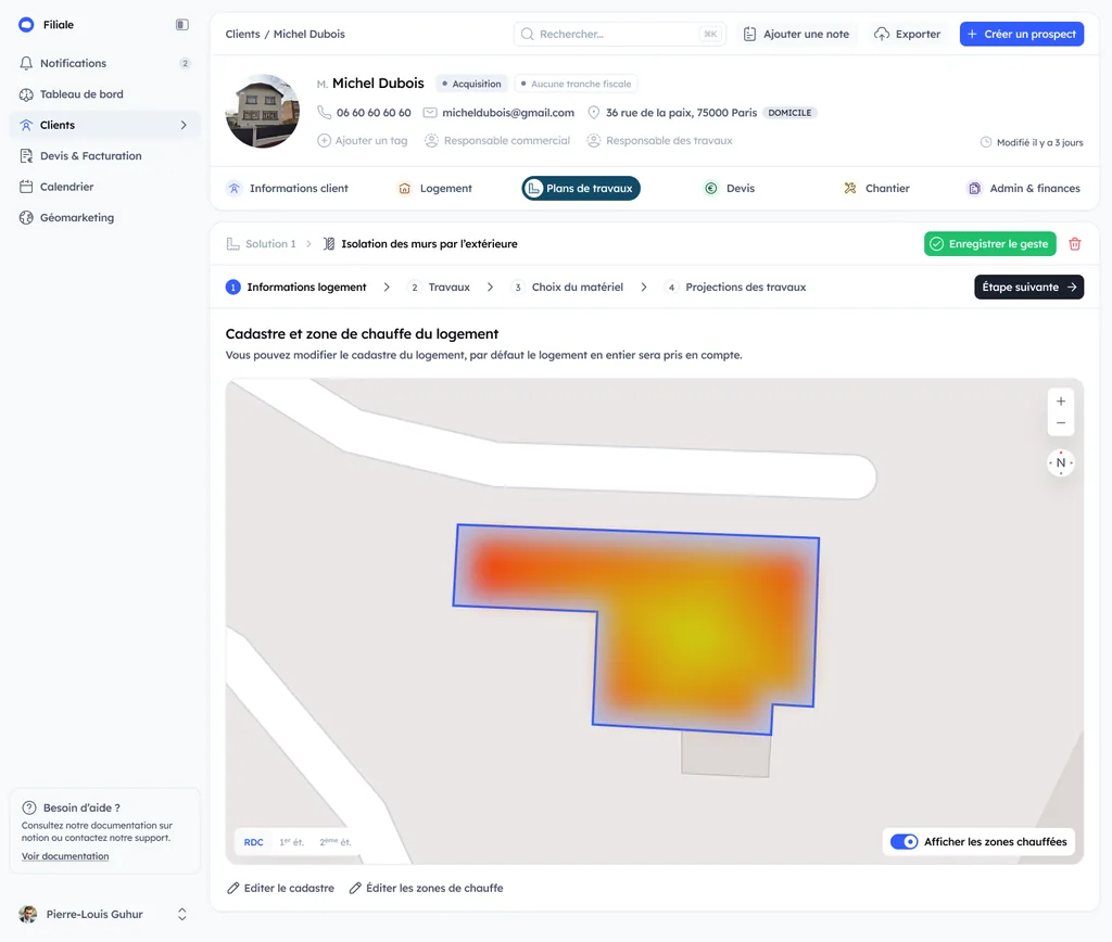
U isn't just about the bill. It also describes the cold-wall sensation, and therefore comfort near the wall. A poorly insulated wall cools quickly. Water vapour can then condense on a surface that's too cold, especially if ventilation is insufficient or thermal bridges exist. It is these U-values, wall by wall, that feed the heat loss calculation Argile recalculates room by room to NF EN 12831-1.
Don't confuse U, R and lambda: the key trio in insulation
To compare solutions, remember this trio. Lambda (λ) describes a single material (W/m·K). Resistance R describes a layer or an assembly. The higher R, the better. The U-coefficient describes the entire finished wall, with all its layers, and in practice corresponds to U = 1/R (total R). To go further on the calculation, you can use a thermal resistance calculator suited to walls.
Reading a wall like a pro: composition, thermal bridges and impact on the U-value
Old wall, concrete wall, timber frame: why the same insulation doesn't give the same result
For the same thickness, insulation doesn't "work" the same way on every substrate. A heterogeneous old wall (stone, cob, joints) often has more conductive zones and different moisture behaviour. Concrete is more homogeneous but cold. A timber frame creates studs that break continuity. The result: the final U-value depends on the whole stack-up, the fixings and the airtightness.
Thermal bridges (floors, load-bearing partitions, window reveals): insulation's hidden enemy
Floor-to-facade junctions, load-bearing partitions and window reveals create shortcuts for heat. These thermal bridges lower the surface temperature, increase losses and can trigger condensation. Continuous insulation, with returns at reveals and treatment of slab edges, stops heat "escaping round the edges."
Moisture and vapour barriers: when the thermal performance also depends on water vapour
A damp insulation material insulates less well. Vapour strategy matters as much as the centimetres of insulation. Depending on the wall, you choose a vapour barrier or a hygrovariable membrane, fitted without gaps and compatible with the ventilation. On old walls, a classic trap is blocking vapour in the wrong place.
Calculating and checking a wall's U-value: field method and checkpoints
Calculation method: adding up resistances and accounting for layers
On site, start from the wall's actual layers. For each layer, calculate its resistance R = e/λ (thickness in m, conductivity in W/m.K). Add up all the resistances, then add the surface resistances (Rsi, Rse) depending on the direction of flow. The U-value is then U = 1/Rtotal. Also consider thermal bridges, which can invalidate the calculation if a zone is poorly treated.
Typical values: quick reference points before and after insulation (external/internal)
As an order of magnitude, an uninsulated masonry wall often sits between 1.0 and 2.0 W/m².K. After internal or external insulation with 120 to 160 mm of standard insulation (λ around 0.032 to 0.040), you'd typically aim for 0.20 to 0.35 W/m².K, depending on finishes and thermal bridges.
Here are the figures worth carrying in your head on survey, before any calculation, surface resistances included.
| Wall build-up | U bare, no insulation | U with 120 mm at λ 0.035 | U with 160 mm at λ 0.032 |
|---|---|---|---|
| Random stone, 500 to 600 mm | 1.7 to 2.3 | 0.25 | 0.18 |
| Solid brick, 300 to 400 mm | 1.8 to 2.4 | 0.25 | 0.19 |
| Timber frame and infill panel | 1.5 to 2.0 | 0.24 | 0.18 |
| Rendered hollow blockwork, 200 mm | 2.2 to 2.8 | 0.26 | 0.19 |
| Cast concrete, 200 mm | 2.8 to 3.3 | 0.26 | 0.19 |
| Hollow clay block, 200 mm | 1.4 to 1.9 | 0.24 | 0.18 |
| Aerated clay block, 370 mm | 0.35 to 0.45 | not applicable | not applicable |
Two readings come out of that table. First, past 120 mm of insulation the substrate barely matters any more: the columns close up between 0.24 and 0.26, because the resistance of the insulation swamps that of the masonry. Second, the saving you can claim therefore rests on the bare U, and that varies by a factor of two across build-ups. Recording the actual make-up of the wall, thickness included, moves the figure you announce far more than adding another 20 mm of insulation.
Site checks: insulation continuity, fixings, junctions and airtightness
To validate on site, keep these key points in mind.
- Continuity of the insulation. No gaps, no compression, careful treatment of reveals.
- Compatible fixings. Density and spacing compliant, cold points limited.
- Sensitive junctions. Floors, load-bearing partitions, joinery, and airtightness with tapes and sealants.
Choosing the right insulation to lower the U-coefficient without nasty surprises
External vs internal insulation: deciding based on the wall, occupancy and facade constraints
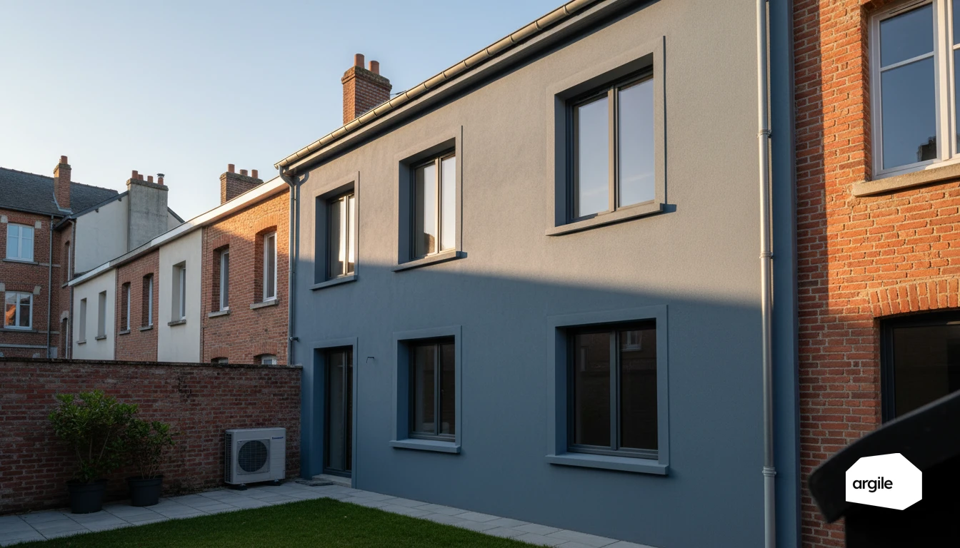
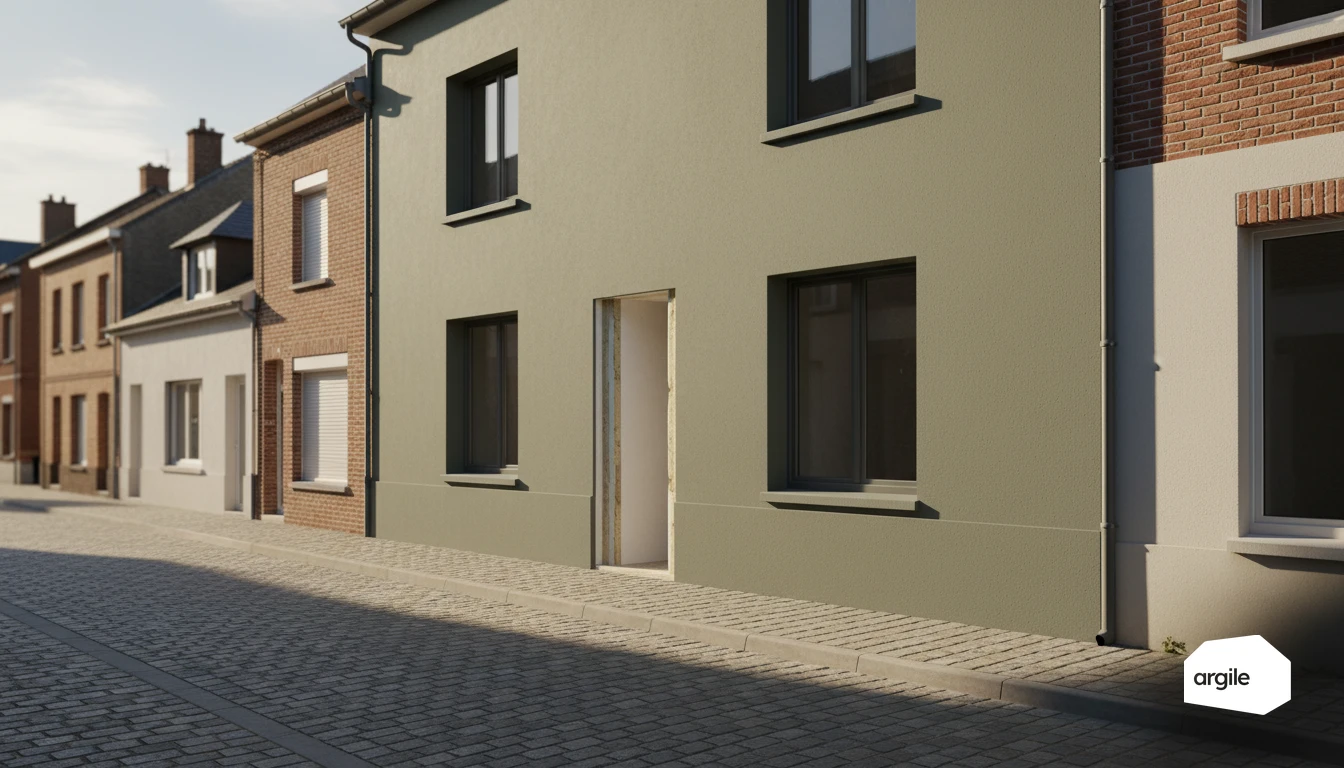
External insulation preserves the wall's thermal mass and limits thermal bridges, but requires a compatible facade (planning rules, co-ownership, overhangs). Internal insulation is easier to carry out in occupied premises, at the cost of lost floor area and a moisture risk if water vapour is poorly managed. Thermal continuity at floors and reveals matters either way. To help decide, you can dig deeper into external vs internal insulation. Once external insulation is chosen, Argile assists the facade take-off, deducts the openings and works out the net areas to insulate.
Insulation materials: mineral wool, bio-based, rigid panels (strengths and limits)
Mineral wool is versatile (cost, acoustics, fire behaviour) but sensitive to water. Bio-based insulation (cellulose, wood fibre) helps with summer comfort and buffers moisture, often requiring more thickness. Rigid panels (EPS, PIR, PUR, XPS) aim for good R in a thin profile. Check ACERMI/DOP certification and fire regulations.
Thickness and performance: reaching a target U-value while managing the details
To lower U, start from lambda (λ) and target a consistent resistance R, then U = 1/total R. The surprises come from the details. Fixings, window sills, roof-wall junctions, air leaks. Work on airtightness, ventilation and a vapour barrier suited to the substrate.
Requirements, aid and RGE practice in 2026: linking the U-coefficient, works and paperwork
2026 reference points: common expectations on wall thermal performance in application files
In 2026, application files mainly expect clearly stated performance. Thermal resistance (R) is the usual metric, and you can easily convert it to a U-coefficient (U = 1/R, outside of complex cases). The simple goal: quote a value consistent with the actual wall, the insulation technique chosen and the treated area.
MaPrimeRénov' and CEE: how to justify wall insulation with the right documents
Key documents: a quote followed by an invoice detailing the wall type, area, insulation material (thickness, lambda, brand and reference), the R or U performance, and the RGE mention. Add technical data sheets or ACERMI certificates, before/after photos, and, for CEE, the signed sworn statement with the works completion date. To limit back-and-forth, also draw on the most common reasons MaPrimeRénov' applications get rejected.
Mistakes that get applications rejected: wall inconsistencies, poorly justified U-coefficient, forgotten thermal bridges
The trap: stating a theoretical U without specifying the assembly (substrate, frame, lining, thermal breaks). Other common reasons for rejection: a different area between the quote and the invoice, an untraceable material, and ignored thermal bridges (reveals, load-bearing partitions, floor junctions). It's better to clearly describe the treatments carried out.