Solar circuit pressure is calculated, not guessed. The expansion vessel precharge is Pprecharge = H/10 + Pmin + Pvapour, where H is the static height in metres between the vessel and the highest point, Pmin the margin at the highest point generally set at 1.5 bar, and Pvapour the vapour pressure of the glycol mixture at the chosen maximum operating temperature, normally between 100 and 130 °C. One metre of water column is 0.1 bar. The final pressure of the vessel is capped at 0.9 times the safety valve setting, so that the valve stays shut in normal operation. Everything else follows from that.
What pressure actually protects on a solar circuit
Holding enough pressure at the highest point
The expansion system does four jobs, and absorbing expansion is only the second. It first holds sufficient pressure in the circuit, then absorbs the expansion of the liquid as temperature rises, compensates the contraction as temperature falls, particularly in frost, so that points which would otherwise fall into vacuum do not draw in air, and finally, when it is sized for it, absorbs the volume of fluid displaced by vaporisation in the collectors. A system that draws in air every winter does not have a vent problem: it has a badly set vessel.
Why pressure rises in stagnation, and why the valve has to lift
In stagnation the collector produces while the store can no longer absorb. High circuit pressure raises the boiling point and delays vaporisation, but a solar system must not act as a steam generator. The valve is there to make the installation safe when it enters sustained stagnation, and its opening then forces a refill and a repressurisation. It is not a one-off event: a valve that has lifted points to an architecture to review, not simply to fluid to top up.
Telling static, fill and setting pressures apart
Three values coexist and are routinely confused on site. Static pressure follows from the height, at 0.1 bar per metre between the vessel and the highest point. Cold fill pressure is P1 = H/10 + Pmin, static plus the margin at the top. The safety valve setting is derived from the fill pressure at the valve, increased by at least 3 bar and depending on the height of the collectors relative to that valve. Reading the gauge without knowing which of those three you are aiming at leads nowhere.
Calculating the precharge without approximation
The data to record before any calculation
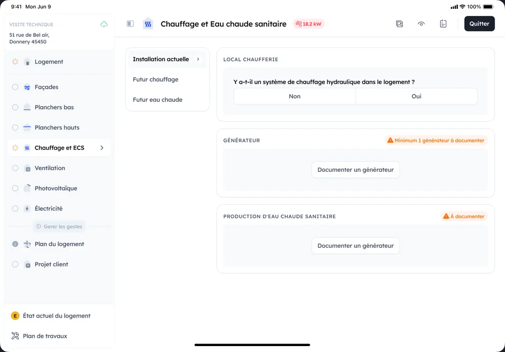
Five items drive the result: the fluid content of the installation, collectors, pipework and exchanger included; the fluid type and its glycol concentration; the maximum operating temperature chosen, generally set between 100 and 130 °C; the static height H from the vessel to the highest point; and the safety valve setting. None of those five can be deduced from a photograph of the plant room, they are recorded on site. Those five items are recorded during the visit, where Argile captures the readings, the photos and the details of the existing installation straight into the file.
The formula and a worked example
The precharge has to overcome the static height and guarantee sufficient pressure everywhere in the circuit under all conditions. It is Pprecharge = H/10 + Pmin + Pvapour, with Pmin generally set at 1.5 bar so that relative pressure at the top of the collectors never falls below vapour pressure, including in hard frost. For a static height of 15 m, a maximum temperature of 120 °C and a fluid at 40 % glycol, that gives 15/10 + 1.5 + 0.6, so 3.6 bar. These pressures are relative: 1.5 bar relative is 2.5 bar absolute.
The vapour pressure table for glycol mixtures
| Maximum operating temperature | 100 °C | 110 °C | 120 °C | 130 °C |
|---|---|---|---|---|
| Fluid at 30 % glycol | 0 bar | 0.3 bar | 0.8 bar | 1.4 bar |
| Fluid at 40 % glycol | 0 bar | 0.2 bar | 0.6 bar | 1.2 bar |
Relative pressures, from the SOCOL technical sheet on the expansion vessel. The usual band of maximum operating temperature sits between 100 and 130 °C, and that choice alone moves the precharge by more than a bar.
Checking pressure on a service visit, in the right order
Measure cold, controls off
The reading is only valid cold, pump stopped, controls off and collectors cooled or covered. Compare the reading with the fill pressure calculated for that installation, not with a generic figure. A persistent shortfall points to a micro-leak or to degassing, an excess points to a saturated vessel or to an isolating valve shut between the vessel and the circuit.
Check the precharge with the vessel isolated
The precharge is measured with the vessel isolated and the water side brought back to zero, never under charge. If water comes out of the valve, the membrane has failed and the vessel is replaced. Also check the expected air permeability of the membrane, below 10 % a year on a properly specified vessel: a vessel losing its nitrogen behaves like an undersized one, and you will meet it again as a weeping safety valve.
Cross-check pressure, flow and temperatures
Stable pressure with a low flow rate shows up as an abnormally wide flow and return temperature difference. Pressure that swings with flow noise points to residual air, often from a blocked automatic air vent. Too small a temperature difference points to a hydraulic short circuit or a badly fitted sensor. Pressure, flow and temperatures are read together, never in isolation.
The limits the valve and the vessel impose
The safety valve and its compliance
NF DTU 65.12 refers the safety valve to the requirements of NF P 52-001, and the safety group of direct circuit installations to EN 1487. Maximum pressure in the collector loop follows directly from the setting chosen. A valve that has lifted several times is replaced rather than reseated: the debris carried through during each opening eventually leaves it weeping permanently.
What sets a solar vessel apart from a heating vessel
A solar vessel has to withstand higher maximum working pressures and higher glycol concentrations, which calls for a more resistant membrane or bladder. The selection criteria are explicit: glycol compatibility, air permeability, a 10 bar working pressure for a 6 bar valve, and a maximum membrane pressure of 6 to 7 bar. Butyl bladders and nitrile membranes meet those requirements. The right reference is picked from the catalogue: Argile keeps the technical characteristics of every reference verified and up to date at pricing time.
Protecting the membrane: location and buffer volume
This is where the two references usefully complement each other. The technical sheet quotes a maximum admissible membrane temperature of around 110 °C, while NF DTU 65.12 P1-2 notes that it is generally only 70 °C and that the mounting arrangement has to allow for that. In both cases the conclusion is the same: the vessel goes low down, downstream of a length of uninsulated pipework or an upstream buffer volume, never close to the collector flow. The condition of the heat transfer fluid depends on the same thermal choices.
Recording readings and framing the contract
The record that makes drift readable
A single reading proves nothing, a series proves everything. Record the same values at every visit, under the same conditions, so that comparison means something.
- Cold pressure measured, fill pressure calculated for the installation, and the gap between the two.
- Precharge measured with the vessel isolated, date of the last membrane check, safety valve setting.
- Discharge marks at the safety group, air noise, and any alarms logged by the controller.
Planning for summer stagnation
Stagnation is prepared for before summer, not during it. Check the vessel volume against the collector content plus 10 %, the dissipation strategy allowed by the manufacturer, and the controller settings. On installations with low summer draw-off, night-time circulation of the primary fluid rejects the excess heat through the collectors, at the cost of extra pump consumption. That is a trade-off to write into the contract, not to improvise in July.
When to call for a deeper inspection
Pressure that falls repeatedly, a valve that discharges, erratic output or a darkened fluid all justify going beyond a pressure check. Have the fluid analysed, check the heat exchanger, collector tightness and the sensors, and revisit the settings behind solar coverage and backup. Across a portfolio, that level of inspection is contracted for, not slipped into a flat-rate visit.