Understanding a 3-way temperature control valve: principle, ports and applications in heating
Identifying ports A, B and AB: what you need to check before installing the valve
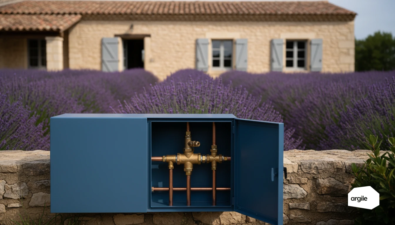
On a 3-way temperature control valve, the ports are cast into the body. AB is usually the common port. Also check the flow arrow and the manufacturer’s schematic. Swapping A and B is enough to make control inconsistent. Plan for actuator accessibility, and check the opening direction against the 0% and 100% position.
Difference between a 3-way temperature control valve in mixing mode and in diverting mode
In mixing mode, the valve modulates the ratio between a hot flow (A) and a cooler return (B) to deliver a stabilized temperature on AB. Controlled by weather-compensated regulation, it produces a flow temperature in line with the heating curve. In diverting mode, the logic is reversed. AB is the inlet and the valve directs flow to A or B, for example for a bypass or a branch circuit.
Where to use it: underfloor heating, radiators, buffer tank, generator protection
Typical applications: mixing for underfloor heating, low-temperature radiators, or charging a buffer tank. For protection, a thermostatic charging valve on a biomass boiler keeps the return hot without electronics. Size the Kvs to maintain proper authority.
Mixing operation: producing a stable flow temperature according to the heating curve
Mixing valve + outdoor sensor control: how the heating curve drives flow temperature
In mixing mode, the 3-way valve takes hot water from the generator flow and a portion of the return, then delivers a flow temperature calculated by the heating curve. The controller reads the outdoor sensor, applies the curve (slope, foot of curve) and compares the setpoint with the measured mixed flow temperature. It then modulates the opening, in 3-point or 0–10 V control, like a 3-way temperature control valve on a radiator or underfloor heating circuit. To go further on curve setting, see set the heating curve.
Actuator and direction of rotation: avoiding opening/closing reversals
Before commissioning, validate the direction of rotation using the actuator’s manual mode. As the setpoint rises, the valve should increase the share of hot water. Also check the end stops, the wiring (open, close, common) and the correspondence with the valve body markings A, B and AB.
Field installation: common mistakes (port reversal, circulator position, bypass)
After-sales call-backs often come down to three points: port reversal, with flow and return swapped; the circulator installed in the wrong place, drawing on AB and disrupting mixing instead of pushing on the mixed flow; and a poorly adjusted bypass, which short-circuits the generator and makes control unstable. Install measurement points upstream and downstream so you can diagnose quickly.
Diverting operation: sending the right flow to the right circuit without upsetting the system balance
When to choose a diverting valve: two outlets, one source, different demands
You have a single source and need to supply two outlets without creating a new temperature. The three-way valve in diverting mode is used to send flow to the priority circuit or to the secondary circuit, or to switch between two heat exchangers. This is typical when each branch has its own downstream control (mixing set, 2-way valve) and you want to control flow share, not the heating curve.
Effects on flow and pressure drop: what the valve is really doing hydraulically
Hydraulically, the 3-way temperature control valve in diverting mode behaves like two variable throttling points. At an intermediate position, you increase the local pressure drop and change the circulator operating point. If valve authority is low or Kvs is too large, control becomes sluggish and the actual distribution drifts depending on branch Δp.
Key checks: balancing, interaction with circulators and isolation valves
- Balance each branch (balancing valves, flow limiters) before adjusting the control law.
- Prevent a branch circulator from forcing flow into the other branch. Install check valves or appropriate hydraulic separation.
- During installation, respect the port markings. Swapping A, B and AB creates stray return flow and unstable control.
Choosing Kvs properly: a simple method for correct authority and stable control
Linking flow rate, ΔP and Kvs: practical calculation from loop flow and available pressure drop
For a loop, start from the design flow rate Q, measured or obtained from sizing. Then note the available ΔP you are willing to “spend” across the valve at nominal flow, in bar. For water, the practical relationship is Q = Kvs × √ΔP. Therefore Kvs = Q / √ΔP.
| Input | Symbol | Unit |
|---|---|---|
| Nominal flow rate | Q | m³/h |
| Pressure drop across the valve at Q | ΔP | bar |
| Required Kvs | Kvs | m³/h |
Valve authority: why an oversized Kvs makes control unstable (the classic trap)
Valve authority is written a = ΔPvalve / (ΔPvalve + ΔPsystem). Aim typically for 0.3 to 0.7. A Kvs that is too large flattens ΔPvalve, authority falls, and the loop starts hunting. On a 3-way temperature control valve in mixing mode, you can spot it quickly. The flow temperature starts to hunt, especially in mid-season.
Commissioning settings: useful travel, actuator time, consistency with the controller
Set the useful travel so the valve operates in the middle of its characteristic, not hard against an end stop. Choose an actuator that matches the inertia of the system, often 60 to 120 s. Check the direction of rotation, the control signal (3-point or 0–10 V) and the controller PID settings. To go further on typical mixing/diverting cases, see 3-way valves and temperature control. That gives you stable action without overcorrection.
Special case: thermostatic charging valve for a wood boiler (without electronic control)
Role: protect the boiler from cold return water and limit condensation/tar formation
On a wood boiler without electronics, the thermostatic charging valve maintains a hot return to the heat exchanger. You limit low-temperature corrosion, condensation and tar formation. You also get a cleaner ramp-up before opening to the distribution system or buffer tank.
Operating principle: thermostatic cartridge, temperature thresholds, recirculation loop
The thermostatic cartridge controls a recirculation loop from flow to return until the temperature reaches its threshold. Then the valve opens progressively to the installation and mixes to keep a minimum return temperature. It is a pre-set 3-way temperature control valve, without an outdoor sensor.
| Cartridge (°C) | Target minimum return (°C) | Use |
|---|---|---|
| 55 | 55 | Wood boiler, anti-condensation |
| 60 | 60 | Common case with buffer tank |
| 65 | 65 | Generators sensitive to tar formation |
2026 best practice: schematic, location, thermometer checks and maintenance
Install it as close as possible to the boiler, on the return side, with a short bypass and a dedicated circulator. Respect the port direction. A reversed installation throws everything off. Use thermometers on flow and return to check that the return stays above the threshold after the warm-up phase. Provide a filter, air vent and cartridge replacement as part of maintenance.