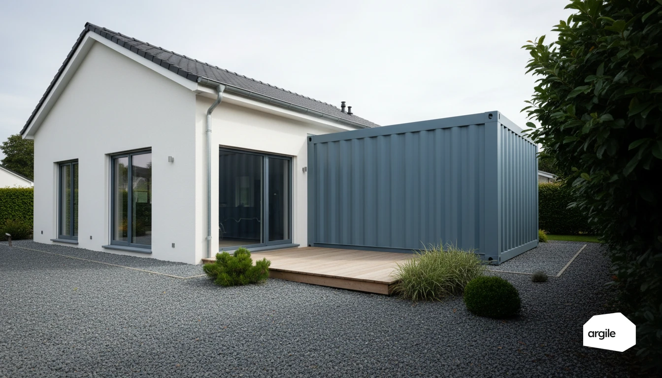
The figure that circulates about container walls, a U-value of 60 W/m²K with no insulation, is physically impossible. The conventional surface resistances of BS EN ISO 6946, 0.13 m²K/W internally and 0.04 externally for horizontal heat flow, on their own cap the U-value of a bare vertical wall at about 5.9 W/m²K, and the plate thickness makes no difference. The practical consequence is more useful than the number: on a container, the whole of the performance comes from the insulation added and from its continuity. And the risk that sends jobs back to the contractor is not the U-value, it is condensation, which BS EN ISO 13788 handles through the internal surface temperature factor.
What a bare container wall is worth
The arithmetic is two surface resistances
BS EN ISO 6946 sets conventional surface resistances by direction of heat flow. Since the steel adds no measurable resistance, those two values are the whole calculation for a bare wall.
| Element | Rsi | Rse | Total R | U-value |
|---|---|---|---|---|
| Wall, horizontal heat flow | 0.13 | 0.04 | 0.17 m²K/W | 5.9 W/m²K |
| Roof, upward heat flow | 0.10 | 0.04 | 0.14 m²K/W | 7.1 W/m²K |
| Floor, downward heat flow | 0.17 | 0.04 | 0.21 m²K/W | 4.8 W/m²K |
Those are ceilings: no building element, whatever its make-up, can show a higher U-value, because the air on either side already offers that much resistance. The standard also notes that for declaring a thermal transmittance, or where the direction of heat flow varies, the horizontal values are the ones to use.
Why the steel thickness makes no difference
At a thermal conductivity of around 50 W/(m·K), 2 mm of plate adds 0.00004 m²K/W, four ten-thousandths of the internal surface resistance. Going from 1.6 to 2 mm does not move the third decimal of the U-value. Plate thickness is a structural and a corrosion figure, never a thermal one. What the conductivity of that steel does do is turn every post, every rail and every corner casting into a hard thermal bridge, to be treated as such and priced with the linear heat loss it carries.
What that changes on the survey
On a container there is no existing element to give credit for: the starting performance is nil, the whole area is to be treated, and the take-off is the quote. Record the areas face by face with openings deducted, then the length of every structural junction, because those linear metres carry the thermal bridges and the accessories. Argile works those areas out from the survey and takes the insulant from the catalogue.
The dominant risk is condensation, not the U-value
The fRsi temperature factor
BS EN ISO 13788 gives the method. The internal surface temperature factor is the ratio of the difference between the surface temperature and the outdoor temperature to the difference between indoor and outdoor temperatures. It is compared against a minimum value that guarantees no surface crosses the critical humidity of 80% relative humidity, the level at which mould grows. On a container insulated internally, every place where the insulation is interrupted, a post, a rail, a corner, drops that factor, and that is where the mould appears first.
Internal, external or hybrid: where the dew point sits
The position of the insulation decides the temperature of the plate in winter. From the inside, the steel stays close to the outdoor temperature, the vapour reaching its cold face condenses, and the insulation gets wet with nothing visible. From the outside, the plate moves to the warm side of the insulation, surface condensation disappears and the structural thermal bridges are cut at the same time. That is the technical reason external insulation is the reference solution on this kind of structure, a point taken further in our piece on the container house.
Vapour control and continuity of the air barrier
Where internal insulation is unavoidable, the vapour control layer becomes the critical component of the package. Fit it on the warm side, continuously, with taped laps, and treat every penetration with a grommet rather than a bead of sealant. Plan the services in a service void in front of the membrane, otherwise every socket box becomes a puncture. Continuity is verified before closing up, not after, and duct sealing matters as much as the fabric, as the hidden losses on ventilation ductwork show.
The thresholds: what regulates and what funds
New element or renovated element, the question to settle first
A container turned into a dwelling is a material change of use, and the Building Regulations apply to it as a dwelling. What still has to be decided is whether each thermal element counts as new or as renovated, because the two routes carry different targets. Settle that before discussing insulation thicknesses: it changes the target U-value, the calculation you have to produce and the evidence building control will ask for.
The limiting U-values
| Route in Approved Document L | Wall | Roof |
|---|---|---|
| Table 4.2, new fabric element in an existing dwelling | 0.18 W/m²K | 0.15 W/m²K |
| Table 4.3, renovated element, internal or external insulation | 0.30 W/m²K improved, 0.70 threshold | 0.16 W/m²K improved, 0.35 threshold |
A bare container wall at 5.9 W/m²K sits an order of magnitude above the 0.70 threshold, so an upgrade is never discretionary. The Approved Document allows a lesser standard only in named cases, for instance where meeting the wall value would cut the internal floor area of the room by more than 5%, and it adds that an upgraded thermal element should generally not exceed 0.7 W/m²K in any event. Where any relaxation is claimed, it is documented, not assumed, in the same spirit as keeping scheme paperwork defensible.
Condensation is a separate requirement
Approved Document L is explicit that when renovating thermal elements the work has to comply with the other parts of Schedule 1, with particular attention to Parts B, C, F and J, and that a lesser thermal standard may be acceptable where the work complies with the requirements on interstitial and surface condensation. Read that the right way round: hitting 0.30 W/m²K with a build-up that traps moisture against the steel is not compliance, it is a defect with a certificate.
What gets checked at completion
Air testing happens before the linings go on
- Blower door test before the internal finish, so leaks are corrected while they are still reachable.
- Visual inspection of membranes, laps and every service penetration.
- Moisture readings on sensitive substrates before the linings are closed.
On a volume as tight as a container the measured figure is rarely the problem; it is the handful of concentrated leaks at the floor, roof and window junctions that carry most of the flow. Method and orders of magnitude are in our piece on air permeability testing.
Ventilation and measured flow rates
A very tight envelope demands ventilation that works, not merely ventilation that is fitted. Ask for the duct sizing, then for measured flow rates at the terminals on handover, and file the data sheets with the handover pack. Without that measurement, the moisture the occupants produce stays in the volume, and the insulation build-up receives it.
Summer comfort
A container combines very low thermal mass with a metal envelope that absorbs solar radiation readily. The effective levers are external: shading in front of the openings, a light finish colour, cross ventilation and night purge. Add mass inside, heavy linings or blockwork partitions, to damp the peaks. A container that performs in winter and is unliveable in August is still a failed job, and that trade-off belongs in the design, not in the handover meeting.