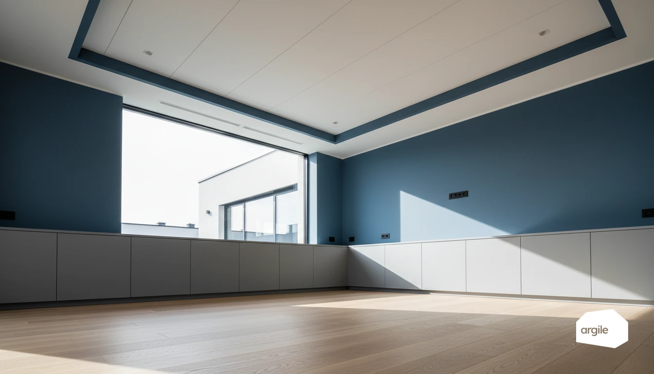
Radiant ceilings have no unified installation code. The electric plasterboard version is governed by CSTB technical prescriptions guide 3636_V2 of November 2009, which caps board temperature at 45°C to prevent the plaster dehydrating, sets maximum rated output at 135 W/m² of active panel area, and requires coverage of at least 40% of the room area. The hydraulic version relies on a technical approval issued system by system, with no common guide. In other words, the figures that bind you are those of the system installed, and they have nothing in common with the 28°C at the finished floor that France imposes on underfloor heating through the order of 23 June 1978.
The framework: what exists and what does not
No unified code, a technical guide and approvals
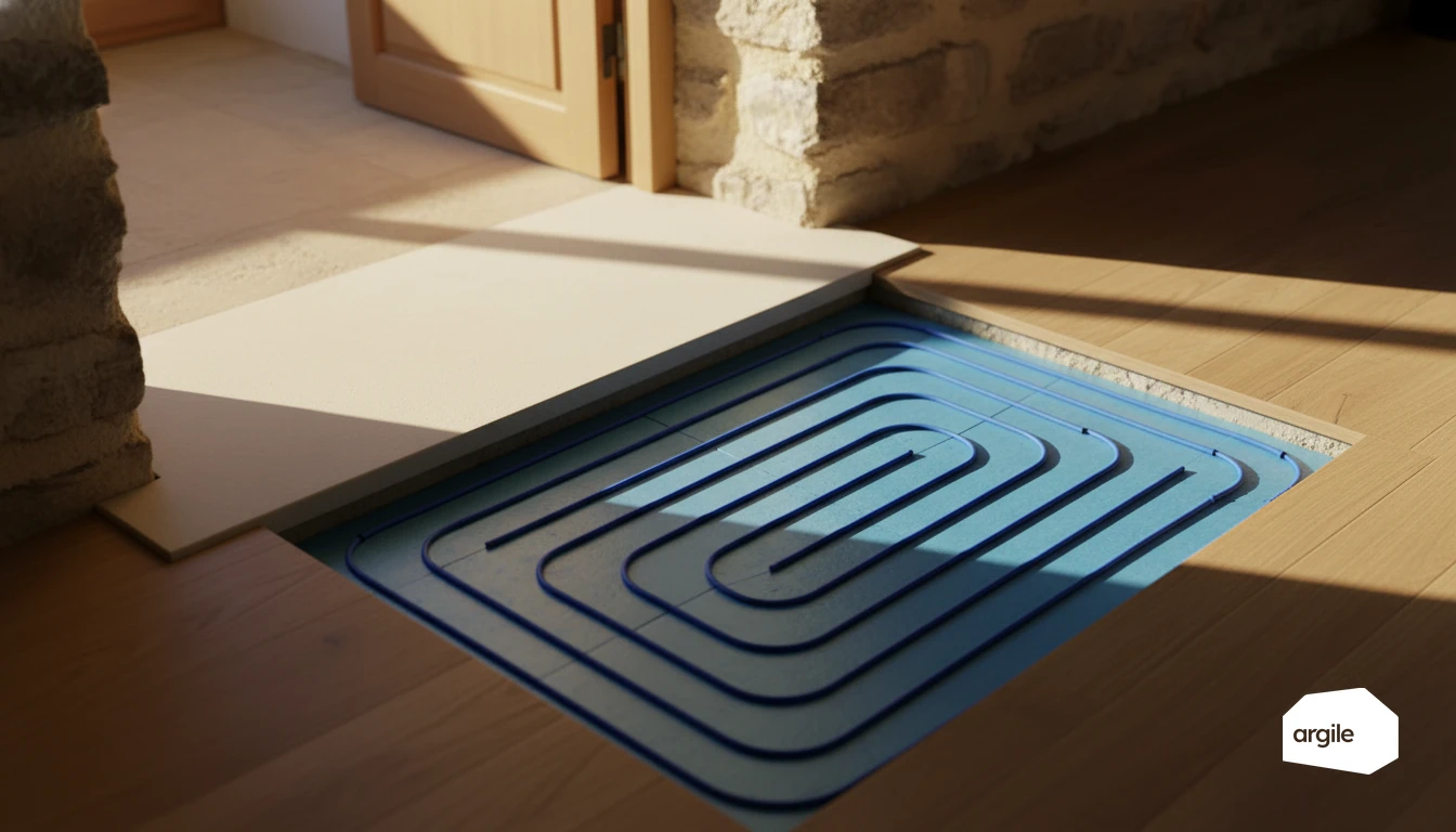
This is the first thing to say to a client comparing two quotations. Water-based underfloor heating is governed by NF DTU 65.14, a traditional and enforceable text. A radiant ceiling is governed by a technical guide for the plasterboard version and a technical approval per system for the hydraulic version. The plasterboard installation code covers only the lining works, notably the mechanical loading of horizontal assemblies, never the heating function.
What that changes for you
Your sizing figures, your temperature limits and your installation rules come from the system actually installed, not from a general rule. In practice, the technical approval is downloaded, annexed to the site file and quoted on the tender. A contractor unable to produce the document for the system it installs is already in default before drilling a single hole.
The plasterboard radiant ceiling figures
| Parameter | Value | Reason or scope |
|---|---|---|
| Maximum surface temperature | 45°C | Plaster dehydration, a material criterion |
| Maximum rated output | 135 W/m² of active area, 12.5 mm board | Relative to the panel, not the ceiling |
| Minimum coverage ratio | 40% of the room area | Evenness of radiation |
| Required headroom in output | Installed output at least 1.2 times the heat loss | Recovery margin |
| Recommended clear headroom | 2.40 m, panel base at least 1.80 m under sloping ceilings | Comfort and asymmetry |
| Distance to surrounding elements | 10 cm from the inner face of partitions, finished walls and beams | Installation |
| Drying before commissioning | 7 days for the joints, 48 h pre-drying heat-up | Durability of the works |
Source: CSTB, guide 3636_V2. Remember that the 135 W/m² figure refers to the active area of the heating panel: it is the most common misreading and it leads to undersizing by a factor of two or three.
Ceiling or floor: the comparison that matters
The ranking reverses between heating and cooling
In heating, the floor wins. In cooling, the ceiling wins, and by a wide margin. The reason is not hydraulic, it is physiological, and it is dealt with in EN ISO 7730 on radiant temperature asymmetry: a warm ceiling produces discomfort at a much smaller difference than a cool one. That asymmetry is what limits a heating ceiling in practice to water temperatures well below the 45 to 55°C the technical approvals allow, those being material limits rather than comfort targets.
The comparison points that belong on the quotation
| Criterion | Water-based underfloor heating | Radiant ceiling |
|---|---|---|
| Framework | NF DTU 65.14, traditional text | CSTB guide 3636_V2 for plasterboard, approval per system |
| Surface temperature | 28°C at the finished floor, order of 23 June 1978 | 45°C board temperature, CSTB guide 3636_V2 |
| Thermal mass | High, carried by the slab | Low, carried by the board |
| Cooling | Weak, below 30 W/m² per institutional publications | Clearly higher than the floor |
| Site constraint | Reservations, screed drying, waiting time before covering | Loss of headroom, drilling reservations |
| Floor covering | Thermal resistance is limiting, capped in reversible use | Not applicable |
Underfloor heating remains the better choice when the slab is being reworked anyway and thermal mass is an advantage, which is set out in our article on sizing a low-temperature floor.
When the ceiling genuinely wins
When the floor cannot be touched, tiling kept, enough headroom available and limited load capacity on an upper floor. When occupancy varies sharply and low thermal mass becomes an asset rather than a defect. And when cooling is genuinely part of the brief, because a cooling floor reaches its ceiling fast, as our article on underfloor cooling sets out.
The hydraulic ceiling: what the technical approvals say
Two systems, two sets of bounds
Technical approval 9/25-1083_V1, valid from 10 September 2025 to 10 September 2027, holds the finished ceiling soffit at no more than 45°C in winter and no less than 18°C in summer, water limited to 45°C in heating and 18°C minimum in cooling, regulated by an aquastat, with a maximum pressure of 6 bar. It refers to NF DTU 65.14 for the temperature limits by geographic zone, to EN 1264-4 for safety and the tightness test, and to EN 14037-5 and EN 14240 for output characterisation in heating and cooling.
The second system, to show the spread
Another hydraulic ceiling approval holds water never above 55°C in heating and never below 15°C in cooling, with a safety thermostat at 18°C, a flow-return difference no greater than 3°C and a surface mass no greater than 25 kg/m². The bounds are therefore not transferable from one system to another, which rules out sizing on a generic figure read somewhere. Here too, the system's own document governs.
The generator that goes with it
A hydraulic ceiling pairs with a heat pump for the same reasons a floor does, with one additional constraint in cooling mode, since chilled water has to be held within a narrow aquastat-regulated range. The generator sizing logic remains the one described in our article on the heat pump and low-temperature emitter pairing, with the room-by-room calculation, which Argile produces to EN 12831-1, and minimum modulated output as the selection criterion.
Site work, handover and the sales argument
Reservations are locked in before closing up
A plan of no-drilling zones, the location of boxes and reinforcements, heavy suspension points, spotlights, hatches, ducts and ventilation terminals. Take a photographic record before lining and hand over an as-built layout drawing. That document is what stops a following trade from drilling through a pipe or a heating element, and it is the one you will be asked for if it happens.
Testing and commissioning
Pressure test for the hydraulic version, electrical checks for the electric version, then bleeding, flow balancing, configuring the controls and a gradual temperature rise. For a plasterboard radiant ceiling, the guide requires 7 days of joint drying and a 48-hour pre-drying heat-up before commissioning proper. These waiting times are planned, they cannot be recovered at the end of a job.
What you state, and what you do not promise
State low thermal mass and responsiveness as a technical choice, not as a quantified performance: no publicly accessible source assigns a radiant ceiling a standardised response time, and the figures in minutes that circulate are not traceable to anything. State output relative to the active panel area. State cooling with the system's soffit bound. On funding applications, the radiant ceiling is the emitter, the insulation and the generator are what carry the money, and consistency between documents remains the leading cause of blocked files, as our article on MaPrimeRénov' application rejections sets out.