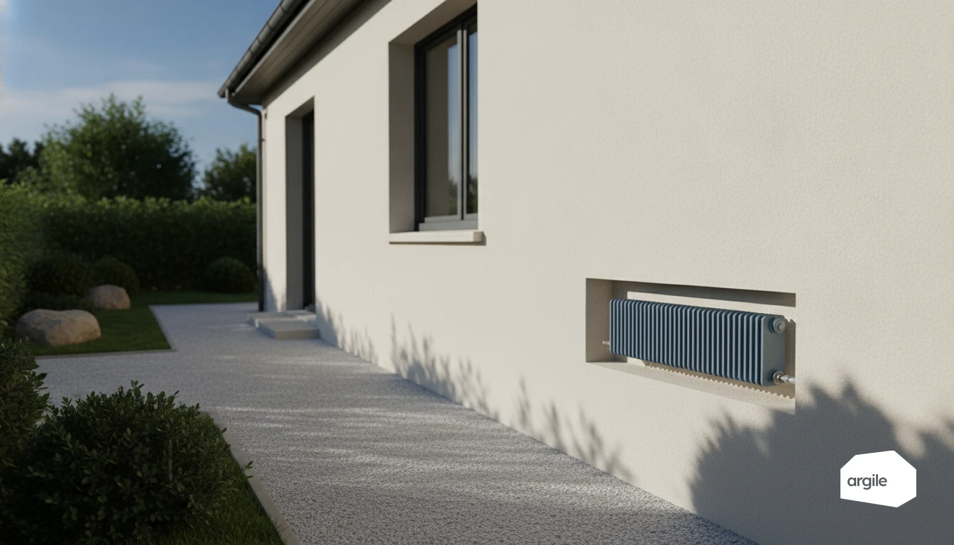
Understanding the role of the emitter in the efficiency of a heating network
Emitter, generator, distribution: who does what, and where efficiency is lost
The generator produces the heat (boiler, heat pump). Distribution carries it through the dwelling via a water network. The emitter (radiator, floor) transmits it to the rooms. Efficiency degrades mainly at the generator (conversion, cycling), then in distribution (pipe heat loss), and finally at the emission stage when the emitter is poorly sized or poorly set. The emission efficiency the DPE assigns to each type of emitter is given in the emission efficiency table by type of emitter.
Flow temperature, water regime and efficiency: the direct link to the emitter
An emitter that heats with cooler water allows the flow temperature to be lowered. As a result, the heat pump works with a better COP and a condensing boiler condenses more often. Conversely, an emitter that is "demanding" on temperature pushes the water regime up, which increases losses and reduces performance.
Common cases in single-family homes: radiators, underfloor heating, fan coil units
- Radiators: often efficient if sized for low temperature and if the heating curve is set correctly.
- Underfloor heating: ideal for low-temperature generators, stable comfort and a low flow temperature.
- Fan coil units: useful when you want a lot of output at moderate temperature, sometimes reversible with a heat pump.
Choosing the right type of emitter based on the existing distribution (and your site constraints)
Low-temperature radiators: when it's relevant and what it changes on the distribution
A low-temperature radiator-type emitter is relevant if you are targeting water at 35 to 45°C, for example with a heat pump. To keep comfort, more exchange surface is often needed. On the distribution side, flow rates go up. Balancing becomes essential, and you need to check diameters, valves, and sometimes the circulator.
Underfloor heating: high efficiency, but points of vigilance (inertia, balancing, pump)
Underfloor heating operates at very low temperature, which improves generator efficiency. In return, its thermal inertia requires well-thought-out controls and stable setpoints. On site, plan for insulation under the slab, available thickness, loop balancing, and a pump or mixing kit if needed. To go further on sizing and pipe spacing, refer to our dedicated guide.
Replacing or keeping the emitters: a decision method that avoids mistakes
To decide, start from a simple method.
- Calculate the heat loss room by room.
- Check the output of each emitter at the target water temperature.
- Check the existing distribution, condition, single-pipe or two-pipe, possibility of balancing.
- Keep it if it works without raising the temperature. Otherwise, replace, or mix solutions.
Calculation method: estimating the impact of emitters on efficiency, distribution and comfort
Simplified calculation of output per room: data to collect during the technical visit
During the visit, record the key data room by room, the inputs of the heat loss calculation. Surface area, ceiling height, walls in contact with the outside, joinery, ventilation, uses. Also note each existing emitter, type, dimensions, thermostatic valves. As a rough order of magnitude, start from a base of 60 to 100 W/m² depending on condition, then adjust for a corner room or a large bay window. The goal is to target a water temperature consistent with the heat pump and the expected level of comfort.
Distribution losses: lengths, insulation, temperatures, circulators (order of magnitude)
Map the distribution. Flow and return lengths, diameters, runs through cold zones, condition of the insulation. An uninsulated network and high flow temperatures can shave off a few percentage points of efficiency, especially in a garage or crawl space. On the auxiliaries side, identify the circulator, its speeds, and the controls. Excess flow increases electricity consumption.
Checking consistency: ΔT, flow rate, balancing and the risk of under-heating
Check the flow-return ΔT and the consistency between output and flow rate. Too low, and it's often unnecessary flow, noise and losses. Too high, and there's a risk of under-heating at the end of the line and discomfort. To check, use Q (m³/h) ≈ P(kW)/(1.16 × ΔT). Finish with balancing, especially if the emitters are of different sizes and circuits.
Optimising efficiency in a whole-house renovation: settings, balancing and 2026 best practices
Hydraulic balancing and heating curve settings: the "easy gain" that changes everything
After insulation and joinery work, review the flow rates and the heating curve. Hydraulic balancing sets each loop to the right flow rate, avoids rooms that are too hot or too cold and lowers return temperatures, which helps a heat pump or a condensing boiler. Adjust the curve gradually, aim for the lowest flow temperature that maintains comfort, then validate over a few days. Easy gain, when done properly.
Networks and accessories: pipe insulation, valves, bleeding, sludge (what drags down efficiency)
An uninsulated network heats the cellar more than the dwelling. Poorly sized valves, air, or sludge cause an emitter's heat exchange to drop and wear out the circulator. Plan for bleeding, a system flush if needed, a magnetic filter, and check the control and safety components. Hidden losses, but very concrete on the bill.
Site action plan: prioritising the works to improve efficiency and comfort
Efficient order. First the envelope, then the generator, then the controls, finally balancing and fine-tuning. On site, measure flow and return temperatures, delta, noise, and consistency between rooms. Give the client a clear setpoint and schedule a check at D+30. Logical order, lasting comfort.
How Argile helps registered tradespeople make emitter choices and efficiency calculations more reliable
Quick energy diagnosis: comparing emitter scenarios in under 5 minutes
Based on the dwelling's data, Argile simulates several generator-emitter pairings. Existing radiators, low-temperature radiators, underfloor heating. You see the impact on flow temperature, consumption and the estimated seasonal efficiency, in 5 minutes.
Feasibility analysis and technical constraints: securing distribution and avoiding sizing errors
The feasibility analysis highlights the key distribution constraints. Pressure losses, hydraulic balance, network length, need for a system flush, compatibility with a low-temperature heat pump. You secure the sizing and avoid an oversized or undersized emitter.
Quotes and funding: costing and an administrative file without losing your evenings
At the quote stage, Argile calculates the line items, integrates the funding the household can draw on according to the project, and prepares the file's documents. You stay in control, but the admin work is handled. The costing stays consistent, without losing your evenings.