Understanding the solar chimney and its value for natural ventilation
The thermal draught principle: sun, duct and chimney effect
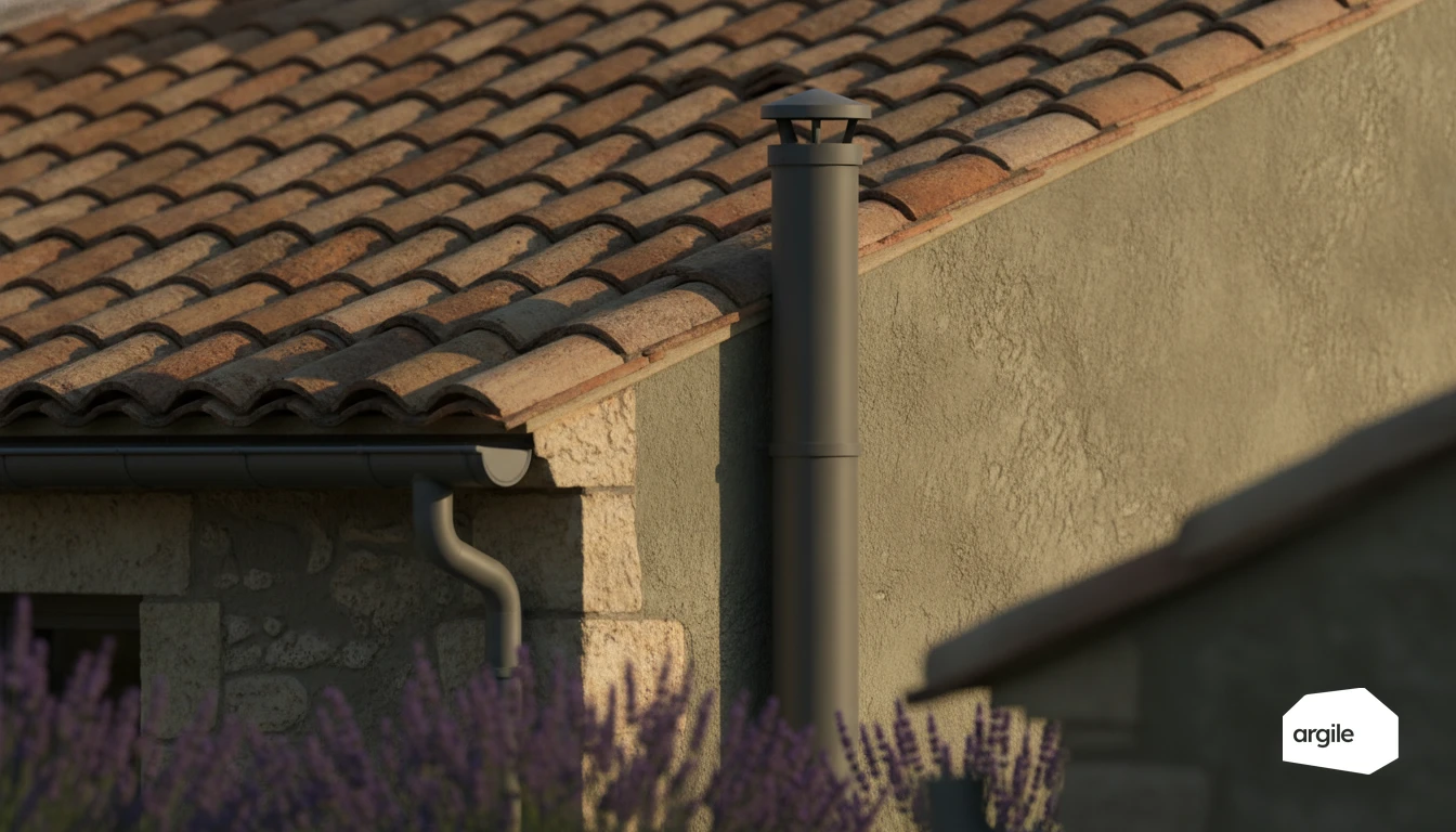
A solar chimney is a dark or glazed duct heated by the sun. The air inside warms up, becomes lighter and rises. This thermal draught creates a low-pressure zone at the bottom of the duct, which draws in fresh air through dedicated air inlets and extracts stale air at the top.
Use cases in renovation: as a boost to mechanical ventilation or as stand-alone natural ventilation
In renovation, it mainly serves as a boost to improve air renewal during the shoulder seasons or reduce the running time of mechanical ventilation. As stand-alone natural ventilation, it can suit well-cross-ventilated living rooms, but it remains dependent on sunshine. In wet rooms, keep controlled extraction.
The main variants: roof-mounted, façade-mounted, single or double wall
You'll find it roof-mounted (more stable draught) or façade-mounted (simpler to integrate). Single-wall models are compact. A double-glazed wall with an absorber improves the temperature rise and limits losses, especially if the duct is well insulated and fitted with non-return valves.
Designing and sizing your solar chimney in 2026
The parameters that determine airflow: height, cross-section, orientation and pressure losses
A solar chimney works as a thermal draught. The greater the height and the more the air warms up in the duct, the higher the airflow rate. The cross-section then affects velocity. Too small, and you create losses. Too large, and the flow slows down. Orient the collector to the south and limit bends, overly tight grilles and unnecessary lengths, since each obstacle eats into the pressure.
Choice of materials and finishes: absorber, glazing, insulation and durability
For the absorber, a dark matte metal sheet is simple and effective. On glazing, glass resists UV and scratches better, while polycarbonate is lighter. Insulate the back of the collector box to keep the heat in the airflow. Aim for durable materials, protected against corrosion and condensation, with a cleaning hatch.
A pragmatic sizing method: flow-rate targets and quick checks
In 2026, start from a concrete target per room. For example 30 to 60 m³/h for a wet room. Choose a cross-section that keeps velocity around 0.5 to 1.5 m/s. Do a quick check of the draught. Compare the available pressure to the total losses (inlets, ducts, outlets). Adjust height, cross-section or glazed area, then validate under real conditions.
Draught check
Does your solar chimney actually pull?
The method from the section above, executed: available pressure on one side, pressure losses on the other. Set the height, the collector and the duct: the airflow follows from both, it is not something you pick.
4.0 m
3.0 m²
25 cm
800 W/m²
32 °C
26 °C
0.0 m/s
Air inlets, transfer grilles, bends and terminal. Direct: a straight duct and a free outlet. Loaded: tight grilles, several bends, a damper.
Airflow
124 m³/h
0.55 m/s in the duct
Available pressure
1.03 Pa
A VMC terminal asks for 97 times more
Exchange with outdoors
253 W
The incoming air is warmer than the dwelling: it heats.
Temperature rise in the collector
+26 K
Stack effect
1.03 Pa
Wind pressure
0.00 Pa
Collector doubled
+26 % airflow
253 W imported into the dwelling
It is warmer outside than inside. The airflow is real, but it carries heat in: at this hour a solar chimney does not cool, it heats. This is the point summer comfort does not forgive.
0.55 m/s
The velocity stays in the band the previous section aims for, 0.5 to 1.5 m/s.
97 times less than a VMC terminal
Here is the order of magnitude most sizing notes leave out: the draught is counted in fractions of a pascal, where a VMC network is set around 100 Pa. A solar chimney does not connect to VMC terminals, and one grille too many is enough to stop it.
The useful hour is 4:00
The airflow peaks in the middle of the day, the coolth is there before dawn, and the two do not coincide. The night draught owes nothing to the sun: it comes from the gap between the dwelling and outdoors. For summer comfort what counts is night ventilation, and it needs no collector.
4:00, 238 W of coolth
Teaching model, steady state: stack effect over the chimney height, collector described by its efficiency curve (optical gain minus losses to outdoors, hence stagnation), lumped pressure losses. Outside the model: the duct’s thermal inertia, the dwelling’s own stack effect below the chimney inlet, and any wind configuration other than the unfavourable one. Not contractual: a real design is validated with an anemometer, as the next section says.
An Argile tool
Integrating the solar chimney into the envelope without creating defects
Airflow path through the dwelling: air inlets, penetrations and connections to rooms
A solar chimney only "draws" well if the air has a clear path. Plan for air inlets at the bottom of living rooms, then transfer passages (undercut doors or grilles) toward the areas connected to the duct. Limit lengths and bends, avoid taking air from the attic, and keep controlled flow rates to avoid creating discomfort.
Airtightness and thermal bridges: sensitive points and installation solutions
Every wall penetration is a sensitive point. Treat the duct-to-wall junction with airtight sleeves, suitable adhesive tapes and renders, then ensure insulation continuity around the duct. An insulated sleeve, fixing clamps with a thermal break, and an insulated box on the inside limit cold surfaces and parasitic air leaks.
Managing humidity and condensate: vapour barrier, drainage and protections
Protect the envelope like a rain jacket. On the warm side, connect the vapour barrier or vapour-check membrane properly at the penetrations. On the duct side, plan a drainage path for condensate (slope, collection point), corrosion-resistant materials, and top protections (grille, cowl) that don't block the draught.
Carrying out the installation on site and securing commissioning
Installation steps: solar collector, duct, outlets and valves
For a solar chimney, installation begins with a stable support and roof or façade sealing. Fix the solar collector without a thermal bridge, then connect a rigid, non-combustible air duct. Aim for lasting airtightness on every joint. Plan a protected low air inlet, a rain-protected high outlet, and non-return valves to prevent flow reversal on windy days.
Simple, reliable control: dampers, summer/winter bypass and overheating protection
Keep the control easy to read. Manual or motorised dampers are enough if the position is visible and lockable. Add a summer/winter bypass to limit heat gains in hot periods, and an overheating safeguard that opens a relief outlet or switches to bypass when temperatures run high. Objective: safe operation, even in degraded mode.
Commissioning checks: draught tests, flow-rate measurement and adjustments
At commissioning, check the draught with a smoke test or an anemometer, then measure the flow rates at the grilles. Correct pressure losses, adjust dampers and valves, and record the values on the commissioning sheet. Fine-tuning avoids noise, odours and condensate.
Improving performance and showcasing the solution to your clients
Summer comfort and air quality: concrete indicators to track in 2026
In 2026, your clients want a feel for it, but also proof. Track 3 simple measurements before and after the works. Indoor temperature during hot periods, with the number of hours above a comfort threshold. Humidity, to spot mould risks. And CO2, a good thermometer for air renewal. With these readings, you turn an opinion into a measurable result, without vague promises.
Practical comparison: solar chimney vs mechanical ventilation (cost, maintenance, constraints) by job type
- Solar chimney. Often mid-range cost. Few moving parts. Effective if a draught is possible and the building allows it.
- Single-flow mechanical ventilation. Controlled cost. Regular maintenance of grilles and air inlets. Often the simplest option in renovation.
- Dual-flow mechanical ventilation. Higher cost. Ductwork needed. Relevant when airtightness and insulation are already at the right level.
Consistency with 2026 approaches: retrofit assessment, EPC and renovation argumentation
Tie the solution to a coherent retrofit pathway. The assessment and the EPC address summer comfort, humidity and ventilation, and Approved Document O now assesses overheating risk on new dwellings. Position the solar chimney as a complementary lever, to be validated against the dwelling like every other measure Argile shortlists from the fabric's characteristics and the client's objectives, and put the prerequisites in writing. You secure the decision, and you strengthen your credibility on site.